Category: 01. Tutorial

https://cdn3d.iconscout.com/3d/premium/thumb/video-tutorial-3d-icon-png-download-10844632.png

  • Software Case Tools Overview

    CASE stands for Computer Aided Software Engineering. It means, development and maintenance of software projects with help of various automated software tools.

    CASE Tools

    CASE tools are set of software application programs, which are used to automate SDLC activities. CASE tools are used by software project managers, analysts and engineers to develop software system.

    There are number of CASE tools available to simplify various stages of Software Development Life Cycle such as Analysis tools, Design tools, Project management tools, Database Management tools, Documentation tools are to name a few.

    Use of CASE tools accelerates the development of project to produce desired result and helps to uncover flaws before moving ahead with next stage in software development.

    Components of CASE Tools

    CASE tools can be broadly divided into the following parts based on their use at a particular SDLC stage:

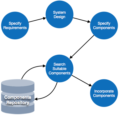
    • Central Repository – CASE tools require a central repository, which can serve as a source of common, integrated and consistent information. Central repository is a central place of storage where product specifications, requirement documents, related reports and diagrams, other useful information regarding management is stored. Central repository also serves as data dictionary.Case Tools
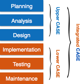
    • Upper Case Tools – Upper CASE tools are used in planning, analysis and design stages of SDLC.
    • Lower Case Tools – Lower CASE tools are used in implementation, testing and maintenance.
    • Integrated Case Tools – Integrated CASE tools are helpful in all the stages of SDLC, from Requirement gathering to Testing and documentation.

    CASE tools can be grouped together if they have similar functionality, process activities and capability of getting integrated with other tools.

    Scope of Case Tools

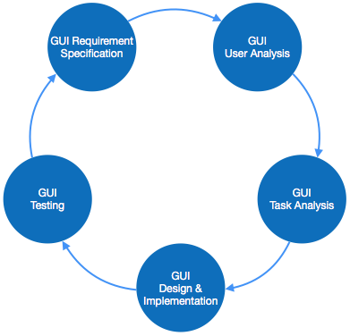
    The scope of CASE tools goes throughout the SDLC.

    Case Tools Types

    Now we briefly go through various CASE tools
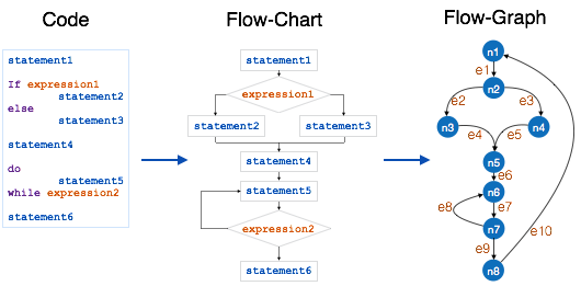
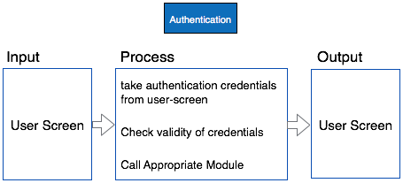
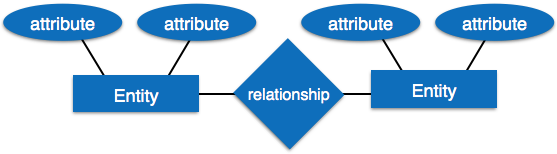
    Diagram tools

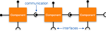
    These tools are used to represent system components, data and control flow among various software components and system structure in a graphical form. For example, Flow Chart Maker tool for creating state-of-the-art flowcharts.

    Process Modeling Tools

    Process modeling is method to create software process model, which is used to develop the software. Process modeling tools help the managers to choose a process model or modify it as per the requirement of software product. For example, EPF Composer

    Project Management Tools

    These tools are used for project planning, cost and effort estimation, project scheduling and resource planning. Managers have to strictly comply project execution with every mentioned step in software project management. Project management tools help in storing and sharing project information in real-time throughout the organization. For example, Creative Pro Office, Trac Project, Basecamp.

    Documentation Tools

    Documentation in a software project starts prior to the software process, goes throughout all phases of SDLC and after the completion of the project.

    Documentation tools generate documents for technical users and end users. Technical users are mostly in-house professionals of the development team who refer to system manual, reference manual, training manual, installation manuals etc. The end user documents describe the functioning and how-to of the system such as user manual. For example, Doxygen, DrExplain, Adobe RoboHelp for documentation.

    Analysis Tools

    These tools help to gather requirements, automatically check for any inconsistency, inaccuracy in the diagrams, data redundancies or erroneous omissions. For example, Accept 360, Accompa, CaseComplete for requirement analysis, Visible Analyst for total analysis.
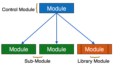
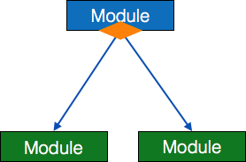
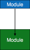
    Design Tools

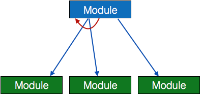
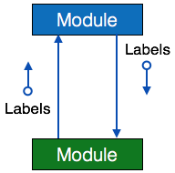
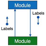
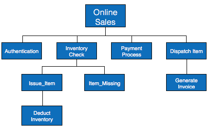
    These tools help software designers to design the block structure of the software, which may further be broken down in smaller modules using refinement techniques. These tools provides detailing of each module and interconnections among modules. For example, Animated Software Design

    Configuration Management Tools

    An instance of software is released under one version. Configuration Management tools deal with

    • Version and revision management
    • Baseline configuration management
    • Change control management

    CASE tools help in this by automatic tracking, version management and release management. For example, Fossil, Git, Accu REV.

    Change Control Tools

    These tools are considered as a part of configuration management tools. They deal with changes made to the software after its baseline is fixed or when the software is first released. CASE tools automate change tracking, file management, code management and more. It also helps in enforcing change policy of the organization.

    Programming Tools

    These tools consist of programming environments like IDE (Integrated Development Environment), in-built modules library and simulation tools. These tools provide comprehensive aid in building software product and include features for simulation and testing. For example, Cscope to search code in C, Eclipse.

    Prototyping Tools

    Software prototype is simulated version of the intended software product. Prototype provides initial look and feel of the product and simulates few aspect of actual product.

    Prototyping CASE tools essentially come with graphical libraries. They can create hardware independent user interfaces and design. These tools help us to build rapid prototypes based on existing information. In addition, they provide simulation of software prototype. For example, Serena prototype composer, Mockup Builder.

    Web Development Tools

    These tools assist in designing web pages with all allied elements like forms, text, script, graphic and so on. Web tools also provide live preview of what is being developed and how will it look after completion. For example, Fontello, Adobe Edge Inspect, Foundation 3, Brackets.

    Quality Assurance Tools

    Quality assurance in a software organization is monitoring the engineering process and methods adopted to develop the software product in order to ensure conformance of quality as per organization standards. QA tools consist of configuration and change control tools and software testing tools. For example, SoapTest, AppsWatch, JMeter.

    Maintenance Tools

    Software maintenance includes modifications in the software product after it is delivered. Automatic logging and error reporting techniques, automatic error ticket generation and root cause Analysis are few CASE tools, which help software organization in maintenance phase of SDLC. For example, Bugzilla for defect tracking, HP Quality Center.

  • Software Maintenance Overview

    Software maintenance is widely accepted part of SDLC now a days. It stands for all the modifications and updations done after the delivery of software product. There are number of reasons, why modifications are required, some of them are briefly mentioned below:

    • Market Conditions – Policies, which changes over the time, such as taxation and newly introduced constraints like, how to maintain bookkeeping, may trigger need for modification.
    • Client Requirements – Over the time, customer may ask for new features or functions in the software.
    • Host Modifications – If any of the hardware and/or platform (such as operating system) of the target host changes, software changes are needed to keep adaptability.
    • Organization Changes – If there is any business level change at client end, such as reduction of organization strength, acquiring another company, organization venturing into new business, need to modify in the original software may arise.

    Types of maintenance

    In a software lifetime, type of maintenance may vary based on its nature. It may be just a routine maintenance tasks as some bug discovered by some user or it may be a large event in itself based on maintenance size or nature. Following are some types of maintenance based on their characteristics:

    • Corrective Maintenance – This includes modifications and updations done in order to correct or fix problems, which are either discovered by user or concluded by user error reports.
    • Adaptive Maintenance – This includes modifications and updations applied to keep the software product up-to date and tuned to the ever changing world of technology and business environment.
    • Perfective Maintenance – This includes modifications and updates done in order to keep the software usable over long period of time. It includes new features, new user requirements for refining the software and improve its reliability and performance.
    • Preventive Maintenance – This includes modifications and updations to prevent future problems of the software. It aims to attend problems, which are not significant at this moment but may cause serious issues in future.

    Cost of Maintenance

    Reports suggest that the cost of maintenance is high. A study on estimating software maintenance found that the cost of maintenance is as high as 67% of the cost of entire software process cycle.

    Maintenance Cost Chart

    On an average, the cost of software maintenance is more than 50% of all SDLC phases. There are various factors, which trigger maintenance cost go high, such as:

    Real-world factors affecting Maintenance Cost

    • The standard age of any software is considered up to 10 to 15 years.
    • Older softwares, which were meant to work on slow machines with less memory and storage capacity cannot keep themselves challenging against newly coming enhanced softwares on modern hardware.
    • As technology advances, it becomes costly to maintain old software.
    • Most maintenance engineers are newbie and use trial and error method to rectify problem.
    • Often, changes made can easily hurt the original structure of the software, making it hard for any subsequent changes.
    • Changes are often left undocumented which may cause more conflicts in future.

    Software-end factors affecting Maintenance Cost

    • Structure of Software Program
    • Programming Language
    • Dependence on external environment
    • Staff reliability and availability

    Maintenance Activities

    IEEE provides a framework for sequential maintenance process activities. It can be used in iterative manner and can be extended so that customized items and processes can be included.

    Maintenance Activities

    These activities go hand-in-hand with each of the following phase:

    • Identification & Tracing – It involves activities pertaining to identification of requirement of modification or maintenance. It is generated by user or system may itself report via logs or error messages.Here, the maintenance type is classified also.
    • Analysis – The modification is analyzed for its impact on the system including safety and security implications. If probable impact is severe, alternative solution is looked for. A set of required modifications is then materialized into requirement specifications. The cost of modification/maintenance is analyzed and estimation is concluded.
    • Design – New modules, which need to be replaced or modified, are designed against requirement specifications set in the previous stage. Test cases are created for validation and verification.
    • Implementation – The new modules are coded with the help of structured design created in the design step.Every programmer is expected to do unit testing in parallel.
    • System Testing – Integration testing is done among newly created modules. Integration testing is also carried out between new modules and the system. Finally the system is tested as a whole, following regressive testing procedures.
    • Acceptance Testing – After testing the system internally, it is tested for acceptance with the help of users. If at this state, user complaints some issues they are addressed or noted to address in next iteration.
    • Delivery – After acceptance test, the system is deployed all over the organization either by small update package or fresh installation of the system. The final testing takes place at client end after the software is delivered.Training facility is provided if required, in addition to the hard copy of user manual.
    • Maintenance management – Configuration management is an essential part of system maintenance. It is aided with version control tools to control versions, semi-version or patch management.

    Software Re-engineering

    When we need to update the software to keep it to the current market, without impacting its functionality, it is called software re-engineering. It is a thorough process where the design of software is changed and programs are re-written.

    Legacy software cannot keep tuning with the latest technology available in the market. As the hardware become obsolete, updating of software becomes a headache. Even if software grows old with time, its functionality does not.

    For example, initially Unix was developed in assembly language. When language C came into existence, Unix was re-engineered in C, because working in assembly language was difficult.

    Other than this, sometimes programmers notice that few parts of software need more maintenance than others and they also need re-engineering.

    Process of Re-Engineering

    Re-Engineering Process

    • Decide what to re-engineer. Is it whole software or a part of it?
    • Perform Reverse Engineering, in order to obtain specifications of existing software.
    • Restructure Program if required. For example, changing function-oriented programs into object-oriented programs.
    • Re-structure data as required.
    • Apply Forward engineering concepts in order to get re-engineered software.

    There are few important terms used in Software re-engineering

    Reverse Engineering

    It is a process to achieve system specification by thoroughly analyzing, understanding the existing system. This process can be seen as reverse SDLC model, i.e. we try to get higher abstraction level by analyzing lower abstraction levels.

    An existing system is previously implemented design, about which we know nothing. Designers then do reverse engineering by looking at the code and try to get the design. With design in hand, they try to conclude the specifications. Thus, going in reverse from code to system specification.

    Reverse Engineering

    Program Restructuring

    It is a process to re-structure and re-construct the existing software. It is all about re-arranging the source code, either in same programming language or from one programming language to a different one. Restructuring can have either source code-restructuring and data-restructuring or both.

    Re-structuring does not impact the functionality of the software but enhance reliability and maintainability. Program components, which cause errors very frequently can be changed, or updated with re-structuring.

    The dependability of software on obsolete hardware platform can be removed via re-structuring.

    Forward Engineering

    Forward engineering is a process of obtaining desired software from the specifications in hand which were brought down by means of reverse engineering. It assumes that there was some software engineering already done in the past.

    Forward engineering is same as software engineering process with only one difference it is carried out always after reverse engineering.

    Forward Engineering

    Component reusability

    A component is a part of software program code, which executes an independent task in the system. It can be a small module or sub-system itself.

    Example

    The login procedures used on the web can be considered as components, printing system in software can be seen as a component of the software.

    Components have high cohesion of functionality and lower rate of coupling, i.e. they work independently and can perform tasks without depending on other modules.

    In OOP, the objects are designed are very specific to their concern and have fewer chances to be used in some other software.

    In modular programming, the modules are coded to perform specific tasks which can be used across number of other software programs.

    There is a whole new vertical, which is based on re-use of software component, and is known as Component Based Software Engineering (CBSE).

    Components

    Re-use can be done at various levels

    • Application level – Where an entire application is used as sub-system of new software.
    • Component level – Where sub-system of an application is used.
    • Modules level – Where functional modules are re-used.Software components provide interfaces, which can be used to establish communication among different components.

    Reuse Process

    Two kinds of method can be adopted: either by keeping requirements same and adjusting components or by keeping components same and modifying requirements.

    Reuse Process
    • Requirement Specification – The functional and non-functional requirements are specified, which a software product must comply to, with the help of existing system, user input or both.
    • Design – This is also a standard SDLC process step, where requirements are defined in terms of software parlance. Basic architecture of system as a whole and its sub-systems are created.
    • Specify Components – By studying the software design, the designers segregate the entire system into smaller components or sub-systems. One complete software design turns into a collection of a huge set of components working together.
    • Search Suitable Components – The software component repository is referred by designers to search for the matching component, on the basis of functionality and intended software requirements..
    • Incorporate Components – All matched components are packed together to shape them as complete software.
  • Software Testing Overview

    Software Testing is evaluation of the software against requirements gathered from users and system specifications. Testing is conducted at the phase level in software development life cycle or at module level in program code. Software testing comprises of Validation and Verification.

    Software Validation

    Validation is process of examining whether or not the software satisfies the user requirements. It is carried out at the end of the SDLC. If the software matches requirements for which it was made, it is validated.

    • Validation ensures the product under development is as per the user requirements.
    • Validation answers the question “Are we developing the product which attempts all that user needs from this software ?”.
    • Validation emphasizes on user requirements.

    Software Verification

    Verification is the process of confirming if the software is meeting the business requirements, and is developed adhering to the proper specifications and methodologies.

    • Verification ensures the product being developed is according to design specifications.
    • Verification answers the question “Are we developing this product by firmly following all design specifications ?”
    • Verifications concentrates on the design and system specifications.

    Target of the test are –

    • Errors – These are actual coding mistakes made by developers. In addition, there is a difference in output of software and desired output, is considered as an error.
    • Fault – When error exists fault occurs. A fault, also known as a bug, is a result of an error which can cause system to fail.
    • Failure – failure is said to be the inability of the system to perform the desired task. Failure occurs when fault exists in the system.

    Manual Vs Automated Testing

    Testing can either be done manually or using an automated testing tool:

    • Manual – This testing is performed without taking help of automated testing tools. The software tester prepares test cases for different sections and levels of the code, executes the tests and reports the result to the manager.Manual testing is time and resource consuming. The tester needs to confirm whether or not right test cases are used. Major portion of testing involves manual testing.
    • Automated This testing is a testing procedure done with aid of automated testing tools. The limitations with manual testing can be overcome using automated test tools.

    A test needs to check if a webpage can be opened in Internet Explorer. This can be easily done with manual testing. But to check if the web-server can take the load of 1 million users, it is quite impossible to test manually.

    There are software and hardware tools which helps tester in conducting load testing, stress testing, regression testing.

    Testing Approaches

    Tests can be conducted based on two approaches

    • Functionality testing
    • Implementation testing

    When functionality is being tested without taking the actual implementation in concern it is known as black-box testing. The other side is known as white-box testing where not only functionality is tested but the way it is implemented is also analyzed.

    Exhaustive tests are the best-desired method for a perfect testing. Every single possible value in the range of the input and output values is tested. It is not possible to test each and every value in real world scenario if the range of values is large.

    Black-box testing

    It is carried out to test functionality of the program. It is also called Behavioral testing. The tester in this case, has a set of input values and respective desired results. On providing input, if the output matches with the desired results, the program is tested ok, and problematic otherwise.

    Black-box Testing

    In this testing method, the design and structure of the code are not known to the tester, and testing engineers and end users conduct this test on the software.

    Black-box testing techniques:

    • Equivalence class – The input is divided into similar classes. If one element of a class passes the test, it is assumed that all the class is passed.
    • Boundary values – The input is divided into higher and lower end values. If these values pass the test, it is assumed that all values in between may pass too.
    • Cause-effect graphing – In both previous methods, only one input value at a time is tested. Cause (input) Effect (output) is a testing technique where combinations of input values are tested in a systematic way.
    • Pair-wise Testing – The behavior of software depends on multiple parameters. In pairwise testing, the multiple parameters are tested pair-wise for their different values.
    • State-based testing – The system changes state on provision of input. These systems are tested based on their states and input.

    White-box testing

    It is conducted to test program and its implementation, in order to improve code efficiency or structure. It is also known as Structural testing.

    White-box testing

    In this testing method, the design and structure of the code are known to the tester. Programmers of the code conduct this test on the code.

    The below are some White-box testing techniques:

    • Control-flow testing – The purpose of the control-flow testing to set up test cases which covers all statements and branch conditions. The branch conditions are tested for both being true and false, so that all statements can be covered.
    • Data-flow testing – This testing technique emphasis to cover all the data variables included in the program. It tests where the variables were declared and defined and where they were used or changed.

    Testing Levels

    Testing itself may be defined at various levels of SDLC. The testing process runs parallel to software development. Before jumping on the next stage, a stage is tested, validated and verified.

    Testing separately is done just to make sure that there are no hidden bugs or issues left in the software. Software is tested on various levels –

    Unit Testing

    While coding, the programmer performs some tests on that unit of program to know if it is error free. Testing is performed under white-box testing approach. Unit testing helps developers decide that individual units of the program are working as per requirement and are error free.

    Integration Testing

    Even if the units of software are working fine individually, there is a need to find out if the units if integrated together would also work without errors. For example, argument passing and data updation etc.

    System Testing

    The software is compiled as product and then it is tested as a whole. This can be accomplished using one or more of the following tests:

    • Functionality testing – Tests all functionalities of the software against the requirement.
    • Performance testing – This test proves how efficient the software is. It tests the effectiveness and average time taken by the software to do desired task. Performance testing is done by means of load testing and stress testing where the software is put under high user and data load under various environment conditions.
    • Security & Portability – These tests are done when the software is meant to work on various platforms and accessed by number of persons.

    Acceptance Testing

    When the software is ready to hand over to the customer it has to go through last phase of testing where it is tested for user-interaction and response. This is important because even if the software matches all user requirements and if user does not like the way it appears or works, it may be rejected.

    • Alpha testing – The team of developer themselves perform alpha testing by using the system as if it is being used in work environment. They try to find out how user would react to some action in software and how the system should respond to inputs.
    • Beta testing – After the software is tested internally, it is handed over to the users to use it under their production environment only for testing purpose. This is not as yet the delivered product. Developers expect that users at this stage will bring minute problems, which were skipped to attend.

    Regression Testing

    Whenever a software product is updated with new code, feature or functionality, it is tested thoroughly to detect if there is any negative impact of the added code. This is known as regression testing.

    Testing Documentation

    Testing documents are prepared at different stages –

    Before Testing

    Testing starts with test cases generation. Following documents are needed for reference

    • SRS document – Functional Requirements document
    • Test Policy document – This describes how far testing should take place before releasing the product.
    • Test Strategy document – This mentions detail aspects of test team, responsibility matrix and rights/responsibility of test manager and test engineer.
    • Traceability Matrix document – This is SDLC document, which is related to requirement gathering process. As new requirements come, they are added to this matrix. These matrices help testers know the source of requirement. They can be traced forward and backward.

    While Being Tested

    The following documents may be required while testing is started and is being done:

    • Test Case document – This document contains list of tests required to be conducted. It includes Unit test plan, Integration test plan, System test plan and Acceptance test plan.
    • Test description – This document is a detailed description of all test cases and procedures to execute them.
    • Test case report – This document contains test case report as a result of the test.
    • Test logs – This document contains test logs for every test case report.

    After Testing

    The following documents may be generated after testing :

    • Test summary – This test summary is collective analysis of all test reports and logs. It summarizes and concludes if the software is ready to be launched. The software is released under version control system if it is ready to launch.

    Testing vs. Quality Control, Quality Assurance and Audit

    We need to understand that software testing is different from software quality assurance, software quality control and software auditing.

    • Software quality assurance – These are software development process monitoring means, by which it is assured that all the measures are taken as per the standards of organization. This monitoring is done to make sure that proper software development methods were followed.
    • Software quality control – This is a system to maintain the quality of software product. It may include functional and non-functional aspects of software product, which enhance the goodwill of the organization. This system makes sure that the customer is receiving quality product for their requirement and the product certified as fit for use.
    • Software audit – This is a review of procedure used by the organization to develop the software. A team of auditors, independent of development team examines the software process, procedure, requirements and other aspects of SDLC. The purpose of software audit is to check that software and its development process, both conform standards, rules and regulations.
  • Software Implementation

    In this chapter, we will study about programming methods, documentation and challenges in software implementation.

    Structured Programming

    In the process of coding, the lines of code keep multiplying, thus, size of the software increases. Gradually, it becomes next to impossible to remember the flow of program. If one forgets how software and its underlying programs, files, procedures are constructed it then becomes very difficult to share, debug and modify the program. The solution to this is structured programming. It encourages the developer to use subroutines and loops instead of using simple jumps in the code, thereby bringing clarity in the code and improving its efficiency Structured programming also helps programmer to reduce coding time and organize code properly.

    Structured programming states how the program shall be coded. Structured programming uses three main concepts:

    • Top-down analysis – A software is always made to perform some rational work. This rational work is known as problem in the software parlance. Thus it is very important that we understand how to solve the problem. Under top-down analysis, the problem is broken down into small pieces where each one has some significance. Each problem is individually solved and steps are clearly stated about how to solve the problem.
    • Modular Programming – While programming, the code is broken down into smaller group of instructions. These groups are known as modules, subprograms or subroutines. Modular programming based on the understanding of top-down analysis. It discourages jumps using goto statements in the program, which often makes the program flow non-traceable. Jumps are prohibited and modular format is encouraged in structured programming.
    • Structured Coding – In reference with top-down analysis, structured coding sub-divides the modules into further smaller units of code in the order of their execution. Structured programming uses control structure, which controls the flow of the program, whereas structured coding uses control structure to organize its instructions in definable patterns.

    Functional Programming

    Functional programming is style of programming language, which uses the concepts of mathematical functions. A function in mathematics should always produce the same result on receiving the same argument. In procedural languages, the flow of the program runs through procedures, i.e. the control of program is transferred to the called procedure. While control flow is transferring from one procedure to another, the program changes its state.

    In procedural programming, it is possible for a procedure to produce different results when it is called with the same argument, as the program itself can be in different state while calling it. This is a property as well as a drawback of procedural programming, in which the sequence or timing of the procedure execution becomes important.

    Functional programming provides means of computation as mathematical functions, which produces results irrespective of program state. This makes it possible to predict the behavior of the program.

    Functional programming uses the following concepts:

    • First class and High-order functions – These functions have capability to accept another function as argument or they return other functions as results.
    • Pure functions – These functions do not include destructive updates, that is, they do not affect any I/O or memory and if they are not in use, they can easily be removed without hampering the rest of the program.
    • Recursion – Recursion is a programming technique where a function calls itself and repeats the program code in it unless some pre-defined condition matches. Recursion is the way of creating loops in functional programming.
    • Strict evaluation – It is a method of evaluating the expression passed to a function as an argument. Functional programming has two types of evaluation methods, strict (eager) or non-strict (lazy). Strict evaluation always evaluates the expression before invoking the function. Non-strict evaluation does not evaluate the expression unless it is needed.
    • -calculus – Most functional programming languages use -calculus as their type systems. -expressions are executed by evaluating them as they occur.

    Common Lisp, Scala, Haskell, Erlang and F# are some examples of functional programming languages.

    Programming style

    Programming style is set of coding rules followed by all the programmers to write the code. When multiple programmers work on the same software project, they frequently need to work with the program code written by some other developer. This becomes tedious or at times impossible, if all developers do not follow some standard programming style to code the program.

    An appropriate programming style includes using function and variable names relevant to the intended task, using well-placed indentation, commenting code for the convenience of reader and overall presentation of code. This makes the program code readable and understandable by all, which in turn makes debugging and error solving easier. Also, proper coding style helps ease the documentation and updation.

    Coding Guidelines

    Practice of coding style varies with organizations, operating systems and language of coding itself.

    The following coding elements may be defined under coding guidelines of an organization:

    • Naming conventions – This section defines how to name functions, variables, constants and global variables.
    • Indenting – This is the space left at the beginning of line, usually 2-8 whitespace or single tab.
    • Whitespace – It is generally omitted at the end of line.
    • Operators – Defines the rules of writing mathematical, assignment and logical operators. For example, assignment operator = should have space before and after it, as in x = 2.
    • Control Structures – The rules of writing if-then-else, case-switch, while-until and for control flow statements solely and in nested fashion.
    • Line length and wrapping – Defines how many characters should be there in one line, mostly a line is 80 characters long. Wrapping defines how a line should be wrapped, if is too long.
    • Functions – This defines how functions should be declared and invoked, with and without parameters.
    • Variables – This mentions how variables of different data types are declared and defined.
    • Comments – This is one of the important coding components, as the comments included in the code describe what the code actually does and all other associated descriptions. This section also helps creating help documentations for other developers.

    Software Documentation

    Software documentation is an important part of software process. A well written document provides a great tool and means of information repository necessary to know about software process. Software documentation also provides information about how to use the product.

    A well-maintained documentation should involve the following documents:

    • Requirement documentation – This documentation works as key tool for software designer, developer and the test team to carry out their respective tasks. This document contains all the functional, non-functional and behavioral description of the intended software.Source of this document can be previously stored data about the software, already running software at the clients end, clients interview, questionnaires and research. Generally it is stored in the form of spreadsheet or word processing document with the high-end software management team.This documentation works as foundation for the software to be developed and is majorly used in verification and validation phases. Most test-cases are built directly from requirement documentation.
    • Software Design documentation – These documentations contain all the necessary information, which are needed to build the software. It contains: (a) High-level software architecture, (b) Software design details, (c) Data flow diagrams, (d) Database designThese documents work as repository for developers to implement the software. Though these documents do not give any details on how to code the program, they give all necessary information that is required for coding and implementation.
    • Technical documentation – These documentations are maintained by the developers and actual coders. These documents, as a whole, represent information about the code. While writing the code, the programmers also mention objective of the code, who wrote it, where will it be required, what it does and how it does, what other resources the code uses, etc.The technical documentation increases the understanding between various programmers working on the same code. It enhances re-use capability of the code. It makes debugging easy and traceable.There are various automated tools available and some comes with the programming language itself. For example java comes JavaDoc tool to generate technical documentation of code.
    • User documentation – This documentation is different from all the above explained. All previous documentations are maintained to provide information about the software and its development process. But user documentation explains how the software product should work and how it should be used to get the desired results.These documentations may include, software installation procedures, how-to guides, user-guides, uninstallation method and special references to get more information like license updation etc.

    Software Implementation Challenges

    There are some challenges faced by the development team while implementing the software. Some of them are mentioned below:

    • Code-reuse – Programming interfaces of present-day languages are very sophisticated and are equipped huge library functions. Still, to bring the cost down of end product, the organization management prefers to re-use the code, which was created earlier for some other software. There are huge issues faced by programmers for compatibility checks and deciding how much code to re-use.
    • Version Management – Every time a new software is issued to the customer, developers have to maintain version and configuration related documentation. This documentation needs to be highly accurate and available on time.
    • Target-Host – The software program, which is being developed in the organization, needs to be designed for host machines at the customers end. But at times, it is impossible to design a software that works on the target machines.
  • Software Design Complexity

    The term complexity stands for state of events or things, which have multiple interconnected links and highly complicated structures. In software programming, as the design of software is realized, the number of elements and their interconnections gradually emerge to be huge, which becomes too difficult to understand at once.

    Software design complexity is difficult to assess without using complexity metrics and measures. Let us see three important software complexity measures.

    Halstead’s Complexity Measures

    In 1977, Mr. Maurice Howard Halstead introduced metrics to measure software complexity. Halsteads metrics depends upon the actual implementation of program and its measures, which are computed directly from the operators and operands from source code, in static manner. It allows to evaluate testing time, vocabulary, size, difficulty, errors, and efforts for C/C++/Java source code.

    According to Halstead, A computer program is an implementation of an algorithm considered to be a collection of tokens which can be classified as either operators or operands. Halstead metrics think a program as sequence of operators and their associated operands.

    He defines various indicators to check complexity of module.

    ParameterMeaning
    n1Number of unique operators
    n2Number of unique operands
    N1Number of total occurrence of operators
    N2Number of total occurrence of operands

    When we select source file to view its complexity details in Metric Viewer, the following result is seen in Metric Report:

    MetricMeaningMathematical Representation
    nVocabularyn1 + n2
    NSizeN1 + N2
    VVolumeLength * Log2 Vocabulary
    DDifficulty(n1/2) * (N1/n2)
    EEffortsDifficulty * Volume
    BErrorsVolume / 3000
    TTesting timeTime = Efforts / S, where S=18 seconds.

    Cyclomatic Complexity Measures

    Every program encompasses statements to execute in order to perform some task and other decision-making statements that decide, what statements need to be executed. These decision-making constructs change the flow of the program.

    If we compare two programs of same size, the one with more decision-making statements will be more complex as the control of program jumps frequently.

    McCabe, in 1976, proposed Cyclomatic Complexity Measure to quantify complexity of a given software. It is graph driven model that is based on decision-making constructs of program such as if-else, do-while, repeat-until, switch-case and goto statements.

    Process to make flow control graph:

    • Break program in smaller blocks, delimited by decision-making constructs.
    • Create nodes representing each of these nodes.
    • Connect nodes as follows:
      • If control can branch from block i to block jDraw an arc
      • From exit node to entry nodeDraw an arc.

    To calculate Cyclomatic complexity of a program module, we use the formula –

    V(G) = e  n + 2
    
    Where
    e is total number of edges
    n is total number of nodes
    
    Cyclomatic Complexity Measures

    The Cyclomatic complexity of the above module is

    e = 10
    n = 8
    Cyclomatic Complexity = 10 - 8 + 2
    
                      = 4

    According to P. Jorgensen, Cyclomatic Complexity of a module should not exceed 10.

    Function Point

    It is widely used to measure the size of software. Function Point concentrates on functionality provided by the system. Features and functionality of the system are used to measure the software complexity.

    Function point counts on five parameters, named as External Input, External Output, Logical Internal Files, External Interface Files, and External Inquiry. To consider the complexity of software each parameter is further categorized as simple, average or complex.

    Function Point

    Let us see parameters of function point:

    External Input

    Every unique input to the system, from outside, is considered as external input. Uniqueness of input is measured, as no two inputs should have same formats. These inputs can either be data or control parameters.

    • Simple – if input count is low and affects less internal files
    • Complex – if input count is high and affects more internal files
    • Average – in-between simple and complex.

    External Output

    All output types provided by the system are counted in this category. Output is considered unique if their output format and/or processing are unique.

    • Simple – if output count is low
    • Complex – if output count is high
    • Average – in between simple and complex.

    Logical Internal Files

    Every software system maintains internal files in order to maintain its functional information and to function properly. These files hold logical data of the system. This logical data may contain both functional data and control data.

    • Simple – if number of record types are low
    • Complex – if number of record types are high
    • Average – in between simple and complex.

    External Interface Files

    Software system may need to share its files with some external software or it may need to pass the file for processing or as parameter to some function. All these files are counted as external interface files.

    • Simple – if number of record types in shared file are low
    • Complex – if number of record types in shared file are high
    • Average – in between simple and complex.

    External Inquiry

    An inquiry is a combination of input and output, where user sends some data to inquire about as input and the system responds to the user with the output of inquiry processed. The complexity of a query is more than External Input and External Output. Query is said to be unique if its input and output are unique in terms of format and data.

    • Simple – if query needs low processing and yields small amount of output data
    • Complex – if query needs high process and yields large amount of output data
    • Average – in between simple and complex.

    Each of these parameters in the system is given weightage according to their class and complexity. The table below mentions the weightage given to each parameter:

    ParameterSimpleAverageComplex
    Inputs346
    Outputs457
    Enquiry346
    Files71015
    Interfaces5710

    The table above yields raw Function Points. These function points are adjusted according to the environment complexity. System is described using fourteen different characteristics:

    • Data communications
    • Distributed processing
    • Performance objectives
    • Operation configuration load
    • Transaction rate
    • Online data entry,
    • End user efficiency
    • Online update
    • Complex processing logic
    • Re-usability
    • Installation ease
    • Operational ease
    • Multiple sites
    • Desire to facilitate changes

    These characteristics factors are then rated from 0 to 5, as mentioned below:

    • No influence
    • Incidental
    • Moderate
    • Average
    • Significant
    • Essential

    All ratings are then summed up as N. The value of N ranges from 0 to 70 (14 types of characteristics x 5 types of ratings). It is used to calculate Complexity Adjustment Factors (CAF), using the following formulae:

    CAF = 0.65 + 0.01N
    

    Then,

    Delivered Function Points (FP)= CAF x Raw FP
    

    This FP can then be used in various metrics, such as:

  • Software User Interface Design

    User interface is the front-end application view to which user interacts in order to use the software. User can manipulate and control the software as well as hardware by means of user interface. Today, user interface is found at almost every place where digital technology exists, right from computers, mobile phones, cars, music players, airplanes, ships etc.

    User interface is part of software and is designed such a way that it is expected to provide the user insight of the software. UI provides fundamental platform for human-computer interaction.

    UI can be graphical, text-based, audio-video based, depending upon the underlying hardware and software combination. UI can be hardware or software or a combination of both.

    The software becomes more popular if its user interface is:

    • Attractive
    • Simple to use
    • Responsive in short time
    • Clear to understand
    • Consistent on all interfacing screens

    UI is broadly divided into two categories:

    • Command Line Interface
    • Graphical User Interface

    Command Line Interface (CLI)

    CLI has been a great tool of interaction with computers until the video display monitors came into existence. CLI is first choice of many technical users and programmers. CLI is minimum interface a software can provide to its users.

    CLI provides a command prompt, the place where the user types the command and feeds to the system. The user needs to remember the syntax of command and its use. Earlier CLI were not programmed to handle the user errors effectively.

    A command is a text-based reference to set of instructions, which are expected to be executed by the system. There are methods like macros, scripts that make it easy for the user to operate.

    CLI uses less amount of computer resource as compared to GUI.

    CLI Elements

    Command Line Interface (CLI)

    A text-based command line interface can have the following elements:

    • Command Prompt – It is text-based notifier that is mostly shows the context in which the user is working. It is generated by the software system.
    • Cursor – It is a small horizontal line or a vertical bar of the height of line, to represent position of character while typing. Cursor is mostly found in blinking state. It moves as the user writes or deletes something.
    • Command – A command is an executable instruction. It may have one or more parameters. Output on command execution is shown inline on the screen. When output is produced, command prompt is displayed on the next line.

    Graphical User Interface

    Graphical User Interface provides the user graphical means to interact with the system. GUI can be combination of both hardware and software. Using GUI, user interprets the software.

    Typically, GUI is more resource consuming than that of CLI. With advancing technology, the programmers and designers create complex GUI designs that work with more efficiency, accuracy and speed.

    GUI Elements

    GUI provides a set of components to interact with software or hardware.

    Every graphical component provides a way to work with the system. A GUI system has following elements such as:

    Graphical User Interface
    • Window – An area where contents of application are displayed. Contents in a window can be displayed in the form of icons or lists, if the window represents file structure. It is easier for a user to navigate in the file system in an exploring window. Windows can be minimized, resized or maximized to the size of screen. They can be moved anywhere on the screen. A window may contain another window of the same application, called child window.
    • Tabs – If an application allows executing multiple instances of itself, they appear on the screen as separate windows. Tabbed Document Interface has come up to open multiple documents in the same window. This interface also helps in viewing preference panel in application. All modern web-browsers use this feature.
    • Menu – Menu is an array of standard commands, grouped together and placed at a visible place (usually top) inside the application window. The menu can be programmed to appear or hide on mouse clicks.
    • Icon – An icon is small picture representing an associated application. When these icons are clicked or double clicked, the application window is opened. Icon displays application and programs installed on a system in the form of small pictures.
    • Cursor – Interacting devices such as mouse, touch pad, digital pen are represented in GUI as cursors. On screen cursor follows the instructions from hardware in almost real-time. Cursors are also named pointers in GUI systems. They are used to select menus, windows and other application features.

    Application specific GUI components

    A GUI of an application contains one or more of the listed GUI elements:

    • Application Window – Most application windows uses the constructs supplied by operating systems but many use their own customer created windows to contain the contents of application.
    • Dialogue Box – It is a child window that contains message for the user and request for some action to be taken. For Example: Application generate a dialogue to get confirmation from user to delete a file.Dialogue Box
    • Text-Box – Provides an area for user to type and enter text-based data.
    • Buttons – They imitate real life buttons and are used to submit inputs to the software.Radio-button
    • Radio-button – Displays available options for selection. Only one can be selected among all offered.
    • Check-box – Functions similar to list-box. When an option is selected, the box is marked as checked. Multiple options represented by check boxes can be selected.
    • List-box – Provides list of available items for selection. More than one item can be selected.List-box

    Other impressive GUI components are:

    • Sliders
    • Combo-box
    • Data-grid
    • Drop-down list

    User Interface Design Activities

    There are a number of activities performed for designing user interface. The process of GUI design and implementation is alike SDLC. Any model can be used for GUI implementation among Waterfall, Iterative or Spiral Model.

    A model used for GUI design and development should fulfill these GUI specific steps.

    GUI Process
    • GUI Requirement Gathering – The designers may like to have list of all functional and non-functional requirements of GUI. This can be taken from user and their existing software solution.
    • User Analysis – The designer studies who is going to use the software GUI. The target audience matters as the design details change according to the knowledge and competency level of the user. If user is technical savvy, advanced and complex GUI can be incorporated. For a novice user, more information is included on how-to of software.
    • Task Analysis – Designers have to analyze what task is to be done by the software solution. Here in GUI, it does not matter how it will be done. Tasks can be represented in hierarchical manner taking one major task and dividing it further into smaller sub-tasks. Tasks provide goals for GUI presentation. Flow of information among sub-tasks determines the flow of GUI contents in the software.
    • GUI Design & implementation – Designers after having information about requirements, tasks and user environment, design the GUI and implements into code and embed the GUI with working or dummy software in the background. It is then self-tested by the developers.
    • Testing – GUI testing can be done in various ways. Organization can have in-house inspection, direct involvement of users and release of beta version are few of them. Testing may include usability, compatibility, user acceptance etc.

    GUI Implementation Tools

    There are several tools available using which the designers can create entire GUI on a mouse click. Some tools can be embedded into the software environment (IDE).

    GUI implementation tools provide powerful array of GUI controls. For software customization, designers can change the code accordingly.

    There are different segments of GUI tools according to their different use and platform.

    Example

    Mobile GUI, Computer GUI, Touch-Screen GUI etc. Here is a list of few tools which come handy to build GUI:

    • FLUID
    • AppInventor (Android)
    • LucidChart
    • Wavemaker
    • Visual Studio

    User Interface Golden rules

    The following rules are mentioned to be the golden rules for GUI design, described by Shneiderman and Plaisant in their book (Designing the User Interface).

    • Strive for consistency – Consistent sequences of actions should be required in similar situations. Identical terminology should be used in prompts, menus, and help screens. Consistent commands should be employed throughout.
    • Enable frequent users to use short-cuts – The users desire to reduce the number of interactions increases with the frequency of use. Abbreviations, function keys, hidden commands, and macro facilities are very helpful to an expert user.
    • Offer informative feedback – For every operator action, there should be some system feedback. For frequent and minor actions, the response must be modest, while for infrequent and major actions, the response must be more substantial.
    • Design dialog to yield closure – Sequences of actions should be organized into groups with a beginning, middle, and end. The informative feedback at the completion of a group of actions gives the operators the satisfaction of accomplishment, a sense of relief, the signal to drop contingency plans and options from their minds, and this indicates that the way ahead is clear to prepare for the next group of actions.
    • Offer simple error handling – As much as possible, design the system so the user will not make a serious error. If an error is made, the system should be able to detect it and offer simple, comprehensible mechanisms for handling the error.
    • Permit easy reversal of actions – This feature relieves anxiety, since the user knows that errors can be undone. Easy reversal of actions encourages exploration of unfamiliar options. The units of reversibility may be a single action, a data entry, or a complete group of actions.
    • Support internal locus of control – Experienced operators strongly desire the sense that they are in charge of the system and that the system responds to their actions. Design the system to make users the initiators of actions rather than the responders.
    • Reduce short-term memory load – The limitation of human information processing in short-term memory requires the displays to be kept simple, multiple page displays be consolidated, window-motion frequency be reduced, and sufficient training time be allotted for codes, mnemonics, and sequences of actions.
  • Software Design Strategies

    Software design is a process to conceptualize the software requirements into software implementation. Software design takes the user requirements as challenges and tries to find optimum solution. While the software is being conceptualized, a plan is chalked out to find the best possible design for implementing the intended solution.

    There are multiple variants of software design. Let us study them briefly:

    Structured Design

    Structured design is a conceptualization of problem into several well-organized elements of solution. It is basically concerned with the solution design. Benefit of structured design is, it gives better understanding of how the problem is being solved. Structured design also makes it simpler for designer to concentrate on the problem more accurately.

    Structured design is mostly based on divide and conquer strategy where a problem is broken into several small problems and each small problem is individually solved until the whole problem is solved.

    The small pieces of problem are solved by means of solution modules. Structured design emphasis that these modules be well organized in order to achieve precise solution.

    These modules are arranged in hierarchy. They communicate with each other. A good structured design always follows some rules for communication among multiple modules, namely –

    Cohesion – grouping of all functionally related elements.

    Coupling – communication between different modules.

    A good structured design has high cohesion and low coupling arrangements.

    Function Oriented Design

    In function-oriented design, the system is comprised of many smaller sub-systems known as functions. These functions are capable of performing significant task in the system. The system is considered as top view of all functions.

    Function oriented design inherits some properties of structured design where divide and conquer methodology is used.

    This design mechanism divides the whole system into smaller functions, which provides means of abstraction by concealing the information and their operation.. These functional modules can share information among themselves by means of information passing and using information available globally.

    Another characteristic of functions is that when a program calls a function, the function changes the state of the program, which sometimes is not acceptable by other modules. Function oriented design works well where the system state does not matter and program/functions work on input rather than on a state.

    Design Process

    • The whole system is seen as how data flows in the system by means of data flow diagram.
    • DFD depicts how functions changes data and state of entire system.
    • The entire system is logically broken down into smaller units known as functions on the basis of their operation in the system.
    • Each function is then described at large.

    Object Oriented Design

    Object oriented design works around the entities and their characteristics instead of functions involved in the software system. This design strategies focuses on entities and its characteristics. The whole concept of software solution revolves around the engaged entities.

    Let us see the important concepts of Object Oriented Design:

    • Objects – All entities involved in the solution design are known as objects. For example, person, banks, company and customers are treated as objects. Every entity has some attributes associated to it and has some methods to perform on the attributes.
    • Classes – A class is a generalized description of an object. An object is an instance of a class. Class defines all the attributes, which an object can have and methods, which defines the functionality of the object.In the solution design, attributes are stored as variables and functionalities are defined by means of methods or procedures.
    • Encapsulation – In OOD, the attributes (data variables) and methods (operation on the data) are bundled together is called encapsulation. Encapsulation not only bundles important information of an object together, but also restricts access of the data and methods from the outside world. This is called information hiding.
    • Inheritance – OOD allows similar classes to stack up in hierarchical manner where the lower or sub-classes can import, implement and re-use allowed variables and methods from their immediate super classes. This property of OOD is known as inheritance. This makes it easier to define specific class and to create generalized classes from specific ones.
    • Polymorphism – OOD languages provide a mechanism where methods performing similar tasks but vary in arguments, can be assigned same name. This is called polymorphism, which allows a single interface performing tasks for different types. Depending upon how the function is invoked, respective portion of the code gets executed.

    Design Process

    Software design process can be perceived as series of well-defined steps. Though it varies according to design approach (function oriented or object oriented, yet It may have the following steps involved:

    • A solution design is created from requirement or previous used system and/or system sequence diagram.
    • Objects are identified and grouped into classes on behalf of similarity in attribute characteristics.
    • Class hierarchy and relation among them is defined.
    • Application framework is defined.

    Software Design Approaches

    Here are two generic approaches for software designing:

    Top Down Design

    We know that a system is composed of more than one sub-systems and it contains a number of components. Further, these sub-systems and components may have their on set of sub-system and components and creates hierarchical structure in the system.

    Top-down design takes the whole software system as one entity and then decomposes it to achieve more than one sub-system or component based on some characteristics. Each sub-system or component is then treated as a system and decomposed further. This process keeps on running until the lowest level of system in the top-down hierarchy is achieved.

    Top-down design starts with a generalized model of system and keeps on defining the more specific part of it. When all components are composed the whole system comes into existence.

    Top-down design is more suitable when the software solution needs to be designed from scratch and specific details are unknown.

    Bottom-up Design

    The bottom up design model starts with most specific and basic components. It proceeds with composing higher level of components by using basic or lower level components. It keeps creating higher level components until the desired system is not evolved as one single component. With each higher level, the amount of abstraction is increased.

    Bottom-up strategy is more suitable when a system needs to be created from some existing system, where the basic primitives can be used in the newer system.

    Both, top-down and bottom-up approaches are not practical individually. Instead, a good combination of both is used.

  • Software Analysis & Design Tools

    Software analysis and design includes all activities, which help the transformation of requirement specification into implementation. Requirement specifications specify all functional and non-functional expectations from the software. These requirement specifications come in the shape of human readable and understandable documents, to which a computer has nothing to do.

    Software analysis and design is the intermediate stage, which helps human-readable requirements to be transformed into actual code.

    Let us see few analysis and design tools used by software designers:

    Data Flow Diagram

    Data flow diagram is graphical representation of flow of data in an information system. It is capable of depicting incoming data flow, outgoing data flow and stored data. The DFD does not mention anything about how data flows through the system.

    There is a prominent difference between DFD and Flowchart. The flowchart depicts flow of control in program modules. DFDs depict flow of data in the system at various levels. DFD does not contain any control or branch elements.

    Types of DFD

    Data Flow Diagrams are either Logical or Physical.

    • Logical DFD – This type of DFD concentrates on the system process, and flow of data in the system.For example in a Banking software system, how data is moved between different entities.
    • Physical DFD – This type of DFD shows how the data flow is actually implemented in the system. It is more specific and close to the implementation.

    DFD Components

    DFD can represent Source, destination, storage and flow of data using the following set of components –

    DFD Components
    • Entities – Entities are source and destination of information data. Entities are represented by a rectangles with their respective names.
    • Process – Activities and action taken on the data are represented by Circle or Round-edged rectangles.
    • Data Storage – There are two variants of data storage – it can either be represented as a rectangle with absence of both smaller sides or as an open-sided rectangle with only one side missing.
    • Data Flow – Movement of data is shown by pointed arrows. Data movement is shown from the base of arrow as its source towards head of the arrow as destination.

    Levels of DFD

    • Level 0 – Highest abstraction level DFD is known as Level 0 DFD, which depicts the entire information system as one diagram concealing all the underlying details. Level 0 DFDs are also known as context level DFDs.
    • Level 1 – The Level 0 DFD is broken down into more specific, Level 1 DFD. Level 1 DFD depicts basic modules in the system and flow of data among various modules. Level 1 DFD also mentions basic processes and sources of information.
    • Level 2 – At this level, DFD shows how data flows inside the modules mentioned in Level 1.Higher level DFDs can be transformed into more specific lower level DFDs with deeper level of understanding unless the desired level of specification is achieved.

    Structure Charts

    Structure chart is a chart derived from Data Flow Diagram. It represents the system in more detail than DFD. It breaks down the entire system into lowest functional modules, describes functions and sub-functions of each module of the system to a greater detail than DFD.

    Structure chart represents hierarchical structure of modules. At each layer a specific task is performed.

    Here are the symbols used in construction of structure charts –

    • Module – It represents process or subroutine or task. A control module branches to more than one sub-module. Library Modules are re-usable and invokable from any module.SC Modules
    • Condition – It is represented by small diamond at the base of module. It depicts that control module can select any of sub-routine based on some condition.SC Condition
    • Jump – An arrow is shown pointing inside the module to depict that the control will jump in the middle of the sub-module.SC Module Jump
    • Loop – A curved arrow represents loop in the module. All sub-modules covered by loop repeat execution of module.SC Loop
    • Data flow – A directed arrow with empty circle at the end represents data flow.SC Dataflow
    • Control flow – A directed arrow with filled circle at the end represents control flow.SC ControlFlow

    HIPO Diagram

    HIPO (Hierarchical Input Process Output) diagram is a combination of two organized method to analyze the system and provide the means of documentation. HIPO model was developed by IBM in year 1970.

    HIPO diagram represents the hierarchy of modules in the software system. Analyst uses HIPO diagram in order to obtain high-level view of system functions. It decomposes functions into sub-functions in a hierarchical manner. It depicts the functions performed by system.

    HIPO diagrams are good for documentation purpose. Their graphical representation makes it easier for designers and managers to get the pictorial idea of the system structure.

    HIPO diagrams

    In contrast to IPO (Input Process Output) diagram, which depicts the flow of control and data in a module, HIPO does not provide any information about data flow or control flow.

    IPO Chart

    Example

    Both parts of HIPO diagram, Hierarchical presentation and IPO Chart are used for structure design of software program as well as documentation of the same.

    Structured English

    Most programmers are unaware of the large picture of software so they only rely on what their managers tell them to do. It is the responsibility of higher software management to provide accurate information to the programmers to develop accurate yet fast code.

    Other forms of methods, which use graphs or diagrams, may are sometimes interpreted differently by different people.

    Hence, analysts and designers of the software come up with tools such as Structured English. It is nothing but the description of what is required to code and how to code it. Structured English helps the programmer to write error-free code.

    Other form of methods, which use graphs or diagrams, may are sometimes interpreted differently by different people. Here, both Structured English and Pseudo-Code tries to mitigate that understanding gap.

    Structured English is the It uses plain English words in structured programming paradigm. It is not the ultimate code but a kind of description what is required to code and how to code it. The following are some tokens of structured programming.

    IF-THEN-ELSE,  
    DO-WHILE-UNTIL
    

    Analyst uses the same variable and data name, which are stored in Data Dictionary, making it much simpler to write and understand the code.

    Example

    We take the same example of Customer Authentication in the online shopping environment. This procedure to authenticate customer can be written in Structured English as:

    Enter Customer_Name
    SEEK Customer_Name in Customer_Name_DB file
    IF Customer_Name found THEN
       Call procedure USER_PASSWORD_AUTHENTICATE()
    ELSE
       PRINT error message
       Call procedure NEW_CUSTOMER_REQUEST()
    ENDIF
    

    The code written in Structured English is more like day-to-day spoken English. It can not be implemented directly as a code of software. Structured English is independent of programming language.

    Pseudo-Code

    Pseudo code is written more close to programming language. It may be considered as augmented programming language, full of comments and descriptions.

    Pseudo code avoids variable declaration but they are written using some actual programming languages constructs, like C, Fortran, Pascal etc.

    Pseudo code contains more programming details than Structured English. It provides a method to perform the task, as if a computer is executing the code.

    Example

    Program to print Fibonacci up to n numbers.

    void function Fibonacci
    Get value of n;
    Set value of a to 1;
    Set value of b to 1;
    Initialize I to 0
    for (i=0; i< n; i++)
    {
       if a greater than b 
       {
    
      Increase b by a;
      Print b;
    } else if b greater than a {
      increase a by b;
      print a;
    } }

    Decision Tables

    A Decision table represents conditions and the respective actions to be taken to address them, in a structured tabular format.

    It is a powerful tool to debug and prevent errors. It helps group similar information into a single table and then by combining tables it delivers easy and convenient decision-making.

    Creating Decision Table

    To create the decision table, the developer must follow basic four steps:

    • Identify all possible conditions to be addressed
    • Determine actions for all identified conditions
    • Create Maximum possible rules
    • Define action for each rule

    Decision Tables should be verified by end-users and can lately be simplified by eliminating duplicate rules and actions.

    Example

    Let us take a simple example of day-to-day problem with our Internet connectivity. We begin by identifying all problems that can arise while starting the internet and their respective possible solutions.

    We list all possible problems under column conditions and the prospective actions under column Actions.

    Conditions/ActionsRules
    ConditionsShows ConnectedNNNNYYYY
    Ping is WorkingNNYYNNYY
    Opens WebsiteYNYNYNYN
    ActionsCheck network cableX
    Check internet routerXXXX
    Restart Web BrowserX
    Contact Service providerXXXXXX
    Do no action

    Table : Decision Table In-house Internet Troubleshooting

    Entity-Relationship Model

    Entity-Relationship model is a type of database model based on the notion of real world entities and relationship among them. We can map real world scenario onto ER database model. ER Model creates a set of entities with their attributes, a set of constraints and relation among them.

    ER Model is best used for the conceptual design of database. ER Model can be represented as follows :

    ER Model
    • Entity – An entity in ER Model is a real world being, which has some properties called attributes. Every attribute is defined by its corresponding set of values, called domain.For example, Consider a school database. Here, a student is an entity. Student has various attributes like name, id, age and class etc.
    • Relationship – The logical association among entities is called relationship. Relationships are mapped with entities in various ways. Mapping cardinalities define the number of associations between two entities.Mapping cardinalities:
      • one to one
      • one to many
      • many to one
      • many to many

    Data Dictionary

    Data dictionary is the centralized collection of information about data. It stores meaning and origin of data, its relationship with other data, data format for usage etc. Data dictionary has rigorous definitions of all names in order to facilitate user and software designers.

    Data dictionary is often referenced as meta-data (data about data) repository. It is created along with DFD (Data Flow Diagram) model of software program and is expected to be updated whenever DFD is changed or updated.

    Requirement of Data Dictionary

    The data is referenced via data dictionary while designing and implementing software. Data dictionary removes any chances of ambiguity. It helps keeping work of programmers and designers synchronized while using same object reference everywhere in the program.

    Data dictionary provides a way of documentation for the complete database system in one place. Validation of DFD is carried out using data dictionary.

    Contents

    Data dictionary should contain information about the following

    • Data Flow
    • Data Structure
    • Data Elements
    • Data Stores
    • Data Processing

    Data Flow is described by means of DFDs as studied earlier and represented in algebraic form as described.

    =Composed of
    {}Repetition
    ()Optional
    +And
    [ / ]Or

    Example

    Address = House No + (Street / Area) + City + State

    Course ID = Course Number + Course Name + Course Level + Course Grades

    Data Elements

    Data elements consist of Name and descriptions of Data and Control Items, Internal or External data stores etc. with the following details:

    • Primary Name
    • Secondary Name (Alias)
    • Use-case (How and where to use)
    • Content Description (Notation etc. )
    • Supplementary Information (preset values, constraints etc.)

    Data Store

    It stores the information from where the data enters into the system and exists out of the system. The Data Store may include –

    • Files
      • Internal to software.
      • External to software but on the same machine.
      • External to software and system, located on different machine.
    • Tables
      • Naming convention
      • Indexing property

    Data Processing

    There are two types of Data Processing:

    • Logical: As user sees it
    • Physical: As software sees it
  • Software Design Basics

    Software design is a process to transform user requirements into some suitable form, which helps the programmer in software coding and implementation.

    For assessing user requirements, an SRS (Software Requirement Specification) document is created whereas for coding and implementation, there is a need of more specific and detailed requirements in software terms. The output of this process can directly be used into implementation in programming languages.

    Software design is the first step in SDLC (Software Design Life Cycle), which moves the concentration from problem domain to solution domain. It tries to specify how to fulfill the requirements mentioned in SRS.

    Software Design Levels

    Software design yields three levels of results:

    • Architectural Design – The architectural design is the highest abstract version of the system. It identifies the software as a system with many components interacting with each other. At this level, the designers get the idea of proposed solution domain.
    • High-level Design- The high-level design breaks the single entity-multiple component concept of architectural design into less-abstracted view of sub-systems and modules and depicts their interaction with each other. High-level design focuses on how the system along with all of its components can be implemented in forms of modules. It recognizes modular structure of each sub-system and their relation and interaction among each other.
    • Detailed Design- Detailed design deals with the implementation part of what is seen as a system and its sub-systems in the previous two designs. It is more detailed towards modules and their implementations. It defines logical structure of each module and their interfaces to communicate with other modules.

    Modularization

    Modularization is a technique to divide a software system into multiple discrete and independent modules, which are expected to be capable of carrying out task(s) independently. These modules may work as basic constructs for the entire software. Designers tend to design modules such that they can be executed and/or compiled separately and independently.

    Modular design unintentionally follows the rules of divide and conquer problem-solving strategy this is because there are many other benefits attached with the modular design of a software.

    Advantage of modularization:

    • Smaller components are easier to maintain
    • Program can be divided based on functional aspects
    • Desired level of abstraction can be brought in the program
    • Components with high cohesion can be re-used again
    • Concurrent execution can be made possible
    • Desired from security aspect

    Concurrency

    Back in time, all software are meant to be executed sequentially. By sequential execution we mean that the coded instruction will be executed one after another implying only one portion of program being activated at any given time. Say, a software has multiple modules, then only one of all the modules can be found active at any time of execution.

    In software design, concurrency is implemented by splitting the software into multiple independent units of execution, like modules and executing them in parallel. In other words, concurrency provides capability to the software to execute more than one part of code in parallel to each other.

    It is necessary for the programmers and designers to recognize those modules, which can be made parallel execution.

    Example

    The spell check feature in word processor is a module of software, which runs along side the word processor itself.

    Coupling and Cohesion

    When a software program is modularized, its tasks are divided into several modules based on some characteristics. As we know, modules are set of instructions put together in order to achieve some tasks. They are though, considered as single entity but may refer to each other to work together. There are measures by which the quality of a design of modules and their interaction among them can be measured. These measures are called coupling and cohesion.

    Cohesion

    Cohesion is a measure that defines the degree of intra-dependability within elements of a module. The greater the cohesion, the better is the program design.

    There are seven types of cohesion, namely

    • Co-incidental cohesion – It is unplanned and random cohesion, which might be the result of breaking the program into smaller modules for the sake of modularization. Because it is unplanned, it may serve confusion to the programmers and is generally not-accepted.
    • Logical cohesion – When logically categorized elements are put together into a module, it is called logical cohesion.
    • Temporal Cohesion – When elements of module are organized such that they are processed at a similar point in time, it is called temporal cohesion.
    • Procedural cohesion – When elements of module are grouped together, which are executed sequentially in order to perform a task, it is called procedural cohesion.
    • Communicational cohesion – When elements of module are grouped together, which are executed sequentially and work on same data (information), it is called communicational cohesion.
    • Sequential cohesion – When elements of module are grouped because the output of one element serves as input to another and so on, it is called sequential cohesion.
    • Functional cohesion – It is considered to be the highest degree of cohesion, and it is highly expected. Elements of module in functional cohesion are grouped because they all contribute to a single well-defined function. It can also be reused.

    Coupling

    Coupling is a measure that defines the level of inter-dependability among modules of a program. It tells at what level the modules interfere and interact with each other. The lower the coupling, the better the program.

    There are five levels of coupling, namely –

    • Content coupling – When a module can directly access or modify or refer to the content of another module, it is called content level coupling.
    • Common coupling- When multiple modules have read and write access to some global data, it is called common or global coupling.
    • Control coupling- Two modules are called control-coupled if one of them decides the function of the other module or changes its flow of execution.
    • Stamp coupling- When multiple modules share common data structure and work on different part of it, it is called stamp coupling.
    • Data coupling- Data coupling is when two modules interact with each other by means of passing data (as parameter). If a module passes data structure as parameter, then the receiving module should use all its components.

    Ideally, no coupling is considered to be the best.

    Design Verification

    The output of software design process is design documentation, pseudo codes, detailed logic diagrams, process diagrams, and detailed description of all functional or non-functional requirements.

    The next phase, which is the implementation of software, depends on all outputs mentioned above.

    It is then becomes necessary to verify the output before proceeding to the next phase. The early any mistake is detected, the better it is or it might not be detected until testing of the product. If the outputs of design phase are in formal notation form, then their associated tools for verification should be used otherwise a thorough design review can be used for verification and validation.

    By structured verification approach, reviewers can detect defects that might be caused by overlooking some conditions. A good design review is important for good software design, accuracy and quality.

  • Software Requirements

    The software requirements are description of features and functionalities of the target system. Requirements convey the expectations of users from the software product. The requirements can be obvious or hidden, known or unknown, expected or unexpected from clients point of view.

    Requirement Engineering

    The process to gather the software requirements from client, analyze and document them is known as requirement engineering.

    The goal of requirement engineering is to develop and maintain sophisticated and descriptive System Requirements Specification document.

    Requirement Engineering Process

    It is a four step process, which includes

    • Feasibility Study
    • Requirement Gathering
    • Software Requirement Specification
    • Software Requirement Validation

    Let us see the process briefly –

    Feasibility study

    When the client approaches the organization for getting the desired product developed, it comes up with rough idea about what all functions the software must perform and which all features are expected from the software.

    Referencing to this information, the analysts does a detailed study about whether the desired system and its functionality are feasible to develop.

    This feasibility study is focused towards goal of the organization. This study analyzes whether the software product can be practically materialized in terms of implementation, contribution of project to organization, cost constraints and as per values and objectives of the organization. It explores technical aspects of the project and product such as usability, maintainability, productivity and integration ability.

    The output of this phase should be a feasibility study report that should contain adequate comments and recommendations for management about whether or not the project should be undertaken.

    Requirement Gathering

    If the feasibility report is positive towards undertaking the project, next phase starts with gathering requirements from the user. Analysts and engineers communicate with the client and end-users to know their ideas on what the software should provide and which features they want the software to include.

    Software Requirement Specification

    SRS is a document created by system analyst after the requirements are collected from various stakeholders.

    SRS defines how the intended software will interact with hardware, external interfaces, speed of operation, response time of system, portability of software across various platforms, maintainability, speed of recovery after crashing, Security, Quality, Limitations etc.

    The requirements received from client are written in natural language. It is the responsibility of system analyst to document the requirements in technical language so that they can be comprehended and useful by the software development team.

    SRS should come up with following features:

    • User Requirements are expressed in natural language.
    • Technical requirements are expressed in structured language, which is used inside the organization.
    • Design description should be written in Pseudo code.
    • Format of Forms and GUI screen prints.
    • Conditional and mathematical notations for DFDs etc.

    Software Requirement Validation

    After requirement specifications are developed, the requirements mentioned in this document are validated. User might ask for illegal, impractical solution or experts may interpret the requirements incorrectly. This results in huge increase in cost if not nipped in the bud. Requirements can be checked against following conditions –

    • If they can be practically implemented
    • If they are valid and as per functionality and domain of software
    • If there are any ambiguities
    • If they are complete
    • If they can be demonstrated

    Requirement Elicitation Process

    Requirement elicitation process can be depicted using the folloiwng diagram:

    Requirement elicitation process
    • Requirements gathering – The developers discuss with the client and end users and know their expectations from the software.
    • Organizing Requirements – The developers prioritize and arrange the requirements in order of importance, urgency and convenience.
    • Negotiation & discussion – If requirements are ambiguous or there are some conflicts in requirements of various stakeholders, if they are, it is then negotiated and discussed with stakeholders. Requirements may then be prioritized and reasonably compromised.The requirements come from various stakeholders. To remove the ambiguity and conflicts, they are discussed for clarity and correctness. Unrealistic requirements are compromised reasonably.
    • Documentation – All formal & informal, functional and non-functional requirements are documented and made available for next phase processing.

    Requirement Elicitation Techniques

    Requirements Elicitation is the process to find out the requirements for an intended software system by communicating with client, end users, system users and others who have a stake in the software system development.

    There are various ways to discover requirements

    Interviews

    Interviews are strong medium to collect requirements. Organization may conduct several types of interviews such as:

    • Structured (closed) interviews, where every single information to gather is decided in advance, they follow pattern and matter of discussion firmly.
    • Non-structured (open) interviews, where information to gather is not decided in advance, more flexible and less biased.
    • Oral interviews
    • Written interviews
    • One-to-one interviews which are held between two persons across the table.
    • Group interviews which are held between groups of participants. They help to uncover any missing requirement as numerous people are involved.

    Surveys

    Organization may conduct surveys among various stakeholders by querying about their expectation and requirements from the upcoming system.

    Questionnaires

    A document with pre-defined set of objective questions and respective options is handed over to all stakeholders to answer, which are collected and compiled.

    A shortcoming of this technique is, if an option for some issue is not mentioned in the questionnaire, the issue might be left unattended.

    Task analysis

    Team of engineers and developers may analyze the operation for which the new system is required. If the client already has some software to perform certain operation, it is studied and requirements of proposed system are collected.

    Domain Analysis

    Every software falls into some domain category. The expert people in the domain can be a great help to analyze general and specific requirements.

    Brainstorming

    An informal debate is held among various stakeholders and all their inputs are recorded for further requirements analysis.

    Prototyping

    Prototyping is building user interface without adding detail functionality for user to interpret the features of intended software product. It helps giving better idea of requirements. If there is no software installed at clients end for developers reference and the client is not aware of its own requirements, the developer creates a prototype based on initially mentioned requirements. The prototype is shown to the client and the feedback is noted. The client feedback serves as an input for requirement gathering.

    Observation

    Team of experts visit the clients organization or workplace. They observe the actual working of the existing installed systems. They observe the workflow at clients end and how execution problems are dealt. The team itself draws some conclusions which aid to form requirements expected from the software.

    Software Requirements Characteristics

    Gathering software requirements is the foundation of the entire software development project. Hence they must be clear, correct and well-defined.

    A complete Software Requirement Specifications must be:

    • Clear
    • Correct
    • Consistent
    • Coherent
    • Comprehensible
    • Modifiable
    • Verifiable
    • Prioritized
    • Unambiguous
    • Traceable
    • Credible source

    Software Requirements

    We should try to understand what sort of requirements may arise in the requirement elicitation phase and what kinds of requirements are expected from the software system.

    Broadly software requirements should be categorized in two categories:

    Functional Requirements

    Requirements, which are related to functional aspect of software fall into this category.

    They define functions and functionality within and from the software system.

    Examples –

    • Search option given to user to search from various invoices.
    • User should be able to mail any report to management.
    • Users can be divided into groups and groups can be given separate rights.
    • Should comply business rules and administrative functions.
    • Software is developed keeping downward compatibility intact.

    Non-Functional Requirements

    Requirements, which are not related to functional aspect of software, fall into this category. They are implicit or expected characteristics of software, which users make assumption of.

    Non-functional requirements include –

    • Security
    • Logging
    • Storage
    • Configuration
    • Performance
    • Cost
    • Interoperability
    • Flexibility
    • Disaster recovery
    • Accessibility

    Requirements are categorized logically as

    • Must Have : Software cannot be said operational without them.
    • Should have : Enhancing the functionality of software.
    • Could have : Software can still properly function with these requirements.
    • Wish list : These requirements do not map to any objectives of software.

    While developing software, Must have must be implemented, Should have is a matter of debate with stakeholders and negation, whereas could have and wish list can be kept for software updates.

    User Interface requirements

    UI is an important part of any software or hardware or hybrid system. A software is widely accepted if it is –

    • easy to operate
    • quick in response
    • effectively handling operational errors
    • providing simple yet consistent user interface

    User acceptance majorly depends upon how user can use the software. UI is the only way for users to perceive the system. A well performing software system must also be equipped with attractive, clear, consistent and responsive user interface. Otherwise the functionalities of software system can not be used in convenient way. A system is said be good if it provides means to use it efficiently. User interface requirements are briefly mentioned below –

    • Content presentation
    • Easy Navigation
    • Simple interface
    • Responsive
    • Consistent UI elements
    • Feedback mechanism
    • Default settings
    • Purposeful layout
    • Strategical use of color and texture.
    • Provide help information
    • User centric approach
    • Group based view settings.

    Software System Analyst

    System analyst in an IT organization is a person, who analyzes the requirement of proposed system and ensures that requirements are conceived and documented properly & correctly. Role of an analyst starts during Software Analysis Phase of SDLC. It is the responsibility of analyst to make sure that the developed software meets the requirements of the client.

    System Analysts have the following responsibilities:

    • Analyzing and understanding requirements of intended software
    • Understanding how the project will contribute in the organization objectives
    • Identify sources of requirement
    • Validation of requirement
    • Develop and implement requirement management plan
    • Documentation of business, technical, process and product requirements
    • Coordination with clients to prioritize requirements and remove and ambiguity
    • Finalizing acceptance criteria with client and other stakeholders

    Software Metrics and Measures

    Software Measures can be understood as a process of quantifying and symbolizing various attributes and aspects of software.

    Software Metrics provide measures for various aspects of software process and software product.

    Software measures are fundamental requirement of software engineering. They not only help to control the software development process but also aid to keep quality of ultimate product excellent.

    According to Tom DeMarco, a (Software Engineer), You cannot control what you cannot measure. By his saying, it is very clear how important software measures are.

    Let us see some software metrics:

    • Size Metrics – LOC (Lines of Code), mostly calculated in thousands of delivered source code lines, denoted as KLOC.Function Point Count is measure of the functionality provided by the software. Function Point count defines the size of functional aspect of software.
    • Complexity Metrics – McCabes Cyclomatic complexity quantifies the upper bound of the number of independent paths in a program, which is perceived as complexity of the program or its modules. It is represented in terms of graph theory concepts by using control flow graph.
    • Quality Metrics – Defects, their types and causes, consequence, intensity of severity and their implications define the quality of product.The number of defects found in development process and number of defects reported by the client after the product is installed or delivered at client-end, define quality of product.
    • Process Metrics – In various phases of SDLC, the methods and tools used, the company standards and the performance of development are software process metrics.
    • Resource Metrics – Effort, time and various resources used, represents metrics for resource measurement.