Category: 03. Entity Relationship

https://cdn3d.iconscout.com/3d/premium/thumb/diagram-3d-icon-png-download-10958623.png

  • Specialization and Generalization in Extended ER Model

    The Enhanced Entity-Relationship (EER) model is used to get more advanced features into database design, and help database designers map real-world scenarios more effectively. There are two core concepts in the EER Model – specialization and generalization – that help refine or abstract the entities and help designers create schemas that are both flexible and intuitive.

    In this chapter, we will throw some light on these two core concepts, specialization and generalization, and highlight how they are different from each other, using practical examples for a better understanding.

    What is Specialization in the Extended ER Model?

    Specialization focuses on dividing a general entity type, or superclass, into smaller, more specific categories called subclasses. This process is quite useful when entities in the superclass have distinct characteristics or relationships, and the relationships only apply to certain members.

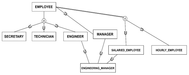
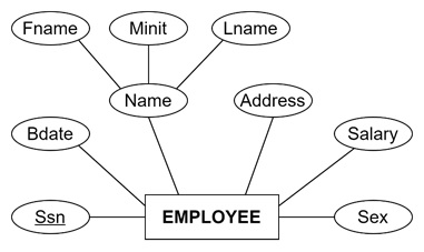
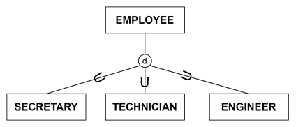
    Specialization is like zooming in on a larger picture to highlight its finer details. Specialization takes a broad category and splits it into meaningful subcategories based on distinguishing attributes or roles. For example, from the EMPLOYEE entity type, we can define subclasses such as SECRETARY, ENGINEER, and TECHNICIAN.

    Specialization in the Extended ER Model

    Types of Specialization

    Specialization could be either attribute-defined or user-defined –

    • Attribute-Defined Specialization − In this type of specialization, the membership in subclasses is determined by the value of a specific attribute in the superclass. Like consider the attribute Job_type in EMPLOYEE. If Job_type = “Technician”, then the employee is part of the TECHNICIAN subclass.
    • User-Defined Specialization − In this type, the subclass membership is manually assigned by users. For example, managers might decide which EMPLOYEES belong to a specific training group.

    Examples of Specialization

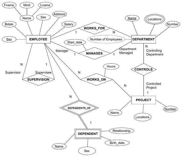
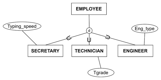
    Let’s consider the company database. EMPLOYEE is specialized into subclasses, such as:

    • SECRETARY with an attribute Typing_speed
    • ENGINEER with an attribute Eng_type
    • TECHNICIAN with attributes like Tgrade
    Examples of Specialization

    These subclasses allow the database to store data more efficiently by associating unique attributes with only the relevant groups.

    Constraints on Specialization

    While working on specializations, we face some constraints. Specialization constraints could be –

    • Disjoint − Entities can belong to only one subclass. Like, an EMPLOYEE cannot simultaneously be a TECHNICIAN and an ENGINEER.
    • Overlapping − Entities can belong to multiple subclasses. For instance, a salaried engineer could belong to both SALARIED_EMPLOYEE and ENGINEER.

    Specializations may also be:

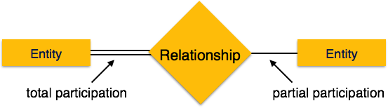
    • Total − Every entity in the superclass must belong to at least one subclass. For example, all EMPLOYEES are either HOURLY_EMPLOYEES or SALARIED_EMPLOYEES.
    • Partial − Some entities may not belong to any subclass. For example, not every EMPLOYEE is a SECRETARY, ENGINEER, or TECHNICIAN.

    What is Generalization in the Extended ER Model?

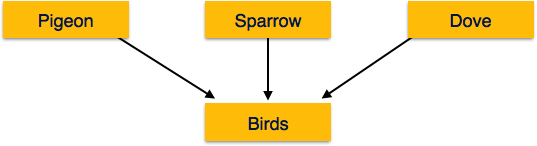
    Generalization combines multiple entity types into a single, broader entity type by identifying shared characteristics. Generalization is like stepping back to see the bigger picture. It suppresses the differences among entities and emphasizes what they have in common.

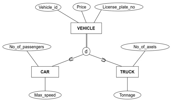
    For instance, in a vehicle database, the CAR and TRUCK share attributes like Vehicle_id and License_plate_no. These can be generalized into a VEHICLE superclass.

    Generalization in the Extended ER Model

    Process of Generalization

    Generalization is simple. All that is needed is to identify common attributes or relationships among two or more entity types. So, we need to define a new superclass that captures these shared features, representing the original entity types as subclasses of the new superclass.

    In the previous transportation database example, we have seen the following –

    Entity Types − CAR and TRUCK

    • CAR has attributes like No_of_passengers.
    • TRUCK has attributes like Tonnage and No_of_axles.

    Here, the VEHICLE includes shared attributes such as Vehicle_id and License_plate_no.

    This approach avoids redundancy by grouping shared data at the superclass level while preserving unique characteristics in the subclasses.

    Combining Specialization and Generalization

    Specialization and generalization are applied within the same database design. These two processes are not mutually exclusive; they are complementary.

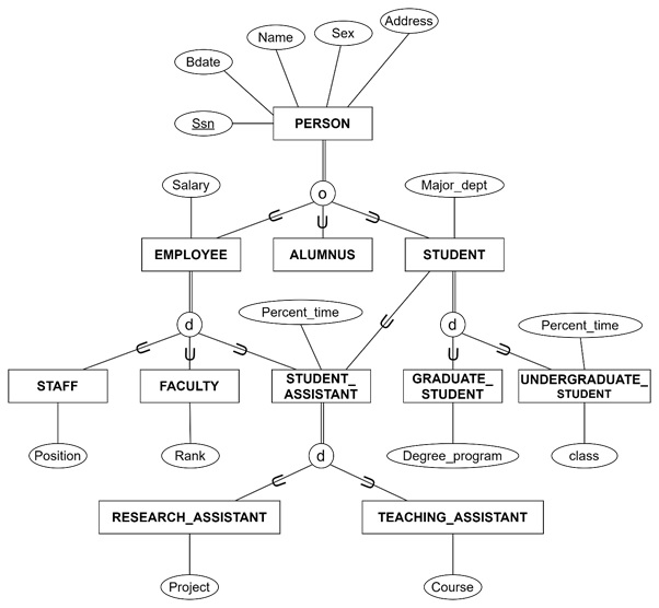
    Consider the university database. Let’s see how specialization and generalization are applied here –

    • Specialization − The PERSON entity type is specialized into STUDENT, EMPLOYEE, and ALUMNUS. EMPLOYEE is further divided into FACULTY, STAFF, and STUDENT_ASSISTANT.
    • Generalization − FACULTY and STAFF are generalized into EMPLOYEE.

    By combining these processes, designers can make a more structured and accurate representation of the data.

    Combining Specialization and Generalization

    Diagrammatic Representation of Specialization and Generalization

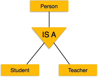
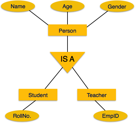
    In EER diagrams, we visualize specialization and generalization clearly.

    Specialization − The superclass connects to subclasses through a circle. The lines indicating subclass relationships. Subclass-specific attributes, such as Typing_speed for SECRETARY, are attached to the respective subclass.

    Generalization − The subclasses connect to the generalized superclass. It highlights shared attributes. For instance:

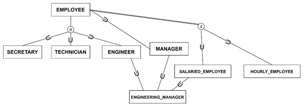
    • In a specialization diagram, EMPLOYEE connects to subclasses like ENGINEER and SECRETARY.
    • In a generalization diagram, CAR and TRUCK converge into a VEHICLE superclass.

    Differences between Specialization and Generalization

    Specialization focuses on highlighting the differences between entities. It breaks down a superclass into specific subclasses. For example: EMPLOYEE → SECRETARY, ENGINEER.

    Generalization emphasizes the commonalities between entities. It combines specific subclasses into a generalized superclass. For example: CAR, TRUCK → VEHICLE.

    Real-World Applications of Specialization and Generalization

    The concepts of specialization and generalization are widely used in various domains:

    Example 1: Company Database

    • Specialization − EMPLOYEE entity type is specialized into categories like SALARIED_EMPLOYEE and HOURLY_EMPLOYEE.
    • Generalization − TEMP_WORKER and PERMANENT_WORKER are generalized into EMPLOYEE.

    Example 2: Vehicle Registration

    • Specialization − VEHICLE entity type is specialized into PASSENGER_CAR and COMMERCIAL_VEHICLE.
    • Generalization − CAR and TRUCK are generalized into VEHICLE.

    Advantages of Specialization and Generalization

    Following are the advantages of using specialization and generalization features in the Extended ER Model –

    • Data Organization − Ensures logical grouping of attributes and relationships, making the database easier to manage.
    • Flexibility − Accommodates both unique and shared characteristics of entities.
    • Efficiency − Reduces redundancy by storing shared attributes in a superclass.
    • Real-World Representation − Mirrors how entities are structured in real life.
  • Subclass, Superclass and Inheritance in EER

    In traditional ER diagrams, we use the entities and their relationships with rectangles and diamonds, respectively. The Enhanced Entity-Relationship (EER) model extends the traditional ER model to support more complex database designs. In EER, we have new concepts such as subclassessuperclasses, and inheritance that are particularly useful in representing real-world entities and their relationships in a structured and hierarchical way. These useful features make EER models suitable for applications like as engineering design, telecommunications, and complex organizational systems.

    In this chapter, we will understand in detail the concepts of subclasses, superclasses, inheritance, and their associated processes of specialization and generalization with examples for a better understanding.

    Subclasses and Superclasses

    superclass shows a broad category of entities, however its subclasses define more specific groupings within that category. The superclass-subclass relationship helps us model hierarchical data.

    For example, consider the EMPLOYEE entity type in a company’s database. It is a broad category that might include subclasses such as:

    • SECRETARY − Employees who handle administrative tasks.
    • TECHNICIAN − Employees who provide technical support or services.
    • ENGINEER − Employees who design and develop systems or products.
    Subclasses and Superclasses EER

    The EMPLOYEE entity type is like the superclass, it has the shared characteristics of all employees. The specific roles like ENGINEER or SECRETARY are the subclasses.

    The Class / Subclass Relationship

    The connection between a superclass and its subclasses is known as the class-subclass relationship. This relationship shows that entities in a subclass are also members of the superclass.

    For example, a TECHNICIAN entity is an EMPLOYEE with additional characteristics specific to the TECHNICIAN role. Similarly, a SECRETARY is an EMPLOYEE but with unique attributes, such as Typing_speed. This relationship is often described using an “is-a” relationship:

    • A TECHNICIAN is an
    • A SECRETARY is an
    The Class / Subclass Relationship

    EER diagrams illustrate these relationships clearly –

    • Like ER diagrams, rectangles represent entities (both superclasses and subclasses).
    • Circles denote specialization or generalization processes.
    • Subset symbols point from subclasses back to their superclass.

    For example, the EMPLOYEE superclass connects to its subclasses through a circle. Specific attributes, like Typing_speed for SECRETARY, are attached to the respective subclass rectangle.

    Inheritance in Superclass-Subclass Relationship

    Inheritance is one of the key features of the superclass-subclass relationship. Inheritance ensures that entities in a subclass retain the attributes and relationships of their superclass. It is used to enables reuse and prevents redundancy.

    Attribute Inheritance

    Entities in a subclass inherit −

    • Superclass Attributes − For instance, all EMPLOYEES might have attributes such as Name, SSN, and Address. These are inherited by subclasses like ENGINEER and TECHNICIAN.
    • Subclass-Specific Attributes − Each subclass has its unique attributes. For example –
      • SECRETARY might have Typing_speed.
      • TECHNICIAN might have Tgrade.

    This hierarchical organization helps ensure that common characteristics remain at the superclass level while allowing subclasses to specialize further.

    Relationship Inheritance

    Subclasses also inherit the relationships of their superclasses. For example, If EMPLOYEE participates in a MANAGES relationship with a PROJECT, all subclasses of EMPLOYEE inherit this relationship.

    This flexibility is useful for subclasses to focus on unique relationships while sharing inherited ones.

    Specialization: Defining Subclasses

    Specialization is the process of dividing a superclass into meaningful subclasses based on specific characteristics. This process is used in designing database schema that reflects real-world distinctions.

    Types of Specialization

    Predicate-Defined Specialization − Subclass membership can be found in conditions on a superclass attribute. Like Subclasses of EMPLOYEE might be defined based on the attribute named “Job_type”:

    • SECRETARY if Job_type = “Secretary”.
    • TECHNICIAN if Job_type = “Technician”.

    User-Defined Specialization − Membership in subclasses is manually assigned by users. This is not determined by predefined conditions.

    Overlapping vs. Disjoint Specialization

    Specializations can be:

    • Disjoint − Entities belong to at most one subclass. For example, An EMPLOYEE can be either HOURLY_EMPLOYEE or SALARIED_EMPLOYEE, but not both.
    • Overlapping − Entities may belong to multiple subclasses. For example: A SALARIED_EMPLOYEE might also be a MANAGER.

    Total vs. Partial Specialization

    • Total Specialization − Every entity in the superclass must belong to at least one subclass. Like every EMPLOYEE must be either HOURLY_EMPLOYEE or SALARIED_EMPLOYEE.
    • Partial Specialization − Some entities in the superclass do not belong to any subclass. Like some EMPLOYEES might not fit into SECRETARY, ENGINEER, or TECHNICIAN subclasses.

    These entities have been represented in the following figure –

    Total vs. Partial Specialization

    Generalization: Abstracting Superclasses

    Generalization is the reverse process of specialization. Generalization identifies common attributes or relationships among multiple entity types and abstracts them into a single superclass.

    For example, consider the following entity types:

    • CAR: Attributes include License_plate_no and Vehicle_id.
    • TRUCK: Attributes include Tonnage and No_of_axles.

    These entities share common attributes like License_plate_no and Vehicle_id. Through generalization, these common attributes can be combined into a VEHICLE superclass, with CAR and TRUCK as its subclasses.

    Combining Specialization and Generalization

    In real-world examples, database design is often used in a mix of specialization and generalization –

    • Specialization refines entity types by breaking them into specific subgroups.
    • Generalization abstracts multiple entity types into broader categories.

    For instance, in a university database:

    • Specialization might divide PERSON into EMPLOYEE, STUDENT, and ALUMNUS.
    • Generalization might combine FACULTY and STAFF into an EMPLOYEE superclass.

    Example: University Database

    Now let us consider a university database to showcase the practical application of these concepts –

    • Superclass − PERSON, with attributes like Name, SSN, Birth_date, and Address.
    • Subclasses −
      • EMPLOYEE − Specialized into FACULTY, STAFF, and STUDENT_ASSISTANT.
      • STUDENT − Specialized into GRADUATE_STUDENT and UNDERGRADUATE_STUDENT.

    Shared Subclasses and Lattices

    Sometimes a subclass belongs to multiple superclasses, forming a shared subclass. For example, STUDENT_ASSISTANT is a subclass of both STUDENT and EMPLOYEE. This creates a lattice structure, where entities inherit attributes from multiple paths.

    For example:

    • A GRADUATE_STUDENT inherits attributes from STUDENT and PERSON.
    • A STUDENT_ASSISTANT inherits from both STUDENT and EMPLOYEE.
    Shared Subclasses and Lattices

    Advantages of Subclasses, Superclasses, and Inheritance

    Following are the advantages of using subclasses, superclasses, and inheritance in Enhanced ER diagrams –

    • Efficient Data Representation − Common attributes are stored in the superclass, reducing redundancy.
    • Flexibility − Subclasses can add specific details while retaining shared attributes and relationships.
    • Real-World Alignment − The hierarchical structure mirrors real-world scenarios, simplifying database design and usage.
  • Enhanced ER (EER) Model

    The ER model is used to visually represent the process of designing a database. There are several components in an ER diagram. We can extend this ER model to some extent to make them more versatile.

    The Enhanced Entity-Relationship (EER) model extends the basic ER model, by adding advanced concepts to represent more complex data structures. This improvement is particularly valuable for modeling databases in fields that demand greater precision. For example engineering, telecommunications, and geographic information systems.

    In this chapter, we will have a look at the main elements of the EER model. In addition, we will touch upon the basics of subclasses, superclasses, inheritance, and specialization. We will cover them in greater detail in the subsequent chapters of this tutorial.

    Basics of the Enhanced ER Model

    The ER model offers foundational tools for creating database schemas. This is useful in many business and industrial applications. But, as database applications evolved, so did the need for more sophisticated modelling tools. That could be represented through complex relationships and data constraints with higher accuracy. The EER model can meet these needs by adding new features such as subclassessuperclassesinheritance, and union types.

    Subclasses and Superclasses

    The EER Model uses concepts such as subclasses and superclasses which are normally used in OOPs programming. A superclass represents a general entity type, while a subclass is a more specific grouping of that entity.

    For instance, consider the EMPLOYEE entity type. Within a company, the EMPLOYEE category could include distinct groups such as SECRETARY, ENGINEER, TECHNICIAN, and MANAGER. Now each of these subgroups forms a subclass of EMPLOYEE.

    Example Diagram − The EER diagram uses a circle to connect subclasses and their superclass. Lines link these entities, illustrating the relationship. In this case, EMPLOYEE is the superclass, while SECRETARY, ENGINEER, and TECHNICIAN are subclasses.

    Subclasses and Superclasses

    Here, the relationship between a superclass and its subclasses is often described as an “IS-A” relationship. This type of relationship means that any instance of a subclass is inherently also an instance of the superclass. Like a SECRETARY entity is also an EMPLOYEE entity in the database. This relationship indicates that a subclass can access all attributes and relationships defined in its superclass.

    Inheritance of Attributes and Relationships

    Inheritance is a popular feature from OOPs programming that allows the entities in a subclass to inherit attributes and relationships from their superclass. For instance, the EMPLOYEE entity type could have common attributes called NameSsn, and Address. The SECRETARY subclass may inherit these attributes while adding its own, such as Typing_speed.

    Inheritance applies to relationships as well. If the EMPLOYEE entity participates in a PROJECT relationship, the SECRETARY subclass will inherit this participation, ensuring a consistent data structure.

    Specialization and Generalization in EER Model

    Specialization and generalization are two related processes in the EER model that refine how entities are categorized.

    Specialization in EER Model

    Specialization shows how to define subsets of an entity type based on distinct attributes or characteristics. In our example, we could create subclasses of EMPLOYEE like HOURLY_EMPLOYEE and SALARIED_EMPLOYEE based on the payment method. This can be done with Pay_scale attribute used for relevant subclass.

    So, the subclasses created through specialization may have specific attributes and relationships that do not apply to the superclass.

    Generalization in EER Model

    Generalization is the opposite of specialization. It combines similar entity types into a broader superclass by identifying shared characteristics. For example, entity types CAR and TRUCK with attributes like License_plate_no and Price could be generalized into a superclass called VEHICLE.

    The entity-specific attributes, such as No_of_axles for TRUCK and Max_speed for CAR, would be retained in their respective subclasses while inheriting common attributes from VEHICLE.

    Constraints in Specialization and Generalization

    Specialization and generalization can include constraints that define how entities belong to subclasses. The two main constraints are explained below –

    • Disjointness Constraint − The disjointness constraint indicates that an entity can be a member of only one subclass. If subclasses are disjoint, the EMPLOYEE cannot be both a SECRETARY and an ENGINEER. This is represented in diagrams by a “d” in the circle connecting subclasses to the superclass. Take a look at the figure below.
    • Completeness Constraint − The completeness constraint is used if an entity must belong to at least one subclass (total specialization) or if it can exist without being in any subclass (partial specialization). There could be a double line between the superclass and the circle to denote a total specialization, while a single line indicates a partial specialization.

    Example − Take a look at the following figure. In Figure 8.1, the specialization {HOURLY_EMPLOYEE, SALARIED_EMPLOYEE} is disjoint and total. Every EMPLOYEE must be either hourly or salaried, but not both.

    Constraints in Specialization and Generalization

    Using Specialization and Generalization in EER Diagrams

    In practice, database designers often use specialization to start with a general entity type and create specific subtypes to handle particular attributes or relationships. Conversely, they may use generalization to combine existing entity types when commonalities are found.

    Advanced Features: Union Types and Categories

    Sometimes, a subclass may need to inherit from more than one superclass. This type of structure is known as a category or union type. This is used when an entity type shares attributes across multiple parent classes. For instance, an OWNER of a vehicle in a registration database might be a PERSON, a BANK, or a COMPANY. The OWNER subclass would be connected to all these superclasses. In the above figure, we are using the “” symbol to represent union relationships.

    Conclusion

    In this chapter, we learned the Enhanced ER model that extends the traditional ER model by incorporating subclasses, superclasses, type inheritance, and specialization or generalization processes. We also reviewed how these features enable more precise and flexible database schemas. We also touched upon constraints such as disjointness and completeness and looked at union types for complex relationships.

  • Drawing an ER Diagram

    Designing a database becomes easier when we use a graphical representation of the entire database. One of the best tools for this is the Entity-Relationship Diagram (ERD). It helps capture important details about entities, their relationships, and any constraints within a business environment.

    In this chapter, we’ll learn how to design an ERD using a real-world example of a COMPANY database. We’ll break down each step, explain the types of entities and relationships, and make the process easy to understand.

    Company Database Tables Design

    We have the following tables in the COMPANY database −

    EMPLOYEE

    FnameMinitLnameSsnBdateAddressSexSalarySuper_ssnDno

    DEPARTMENT

    DnameDnumberMgr_ssnMgr_start_date

    DEPT_LOCATIONS

    DnumberDlocation

    PROJECT

    PnamePnumberPlocationDnum

    WORKS_ON

    EssnPnoHours

    DEPENDENT

    EssnDependent_nameSexBdateRelationship

    Basics of ER Diagram

    To understand the example. Let us see the foundational concepts of an ERD: There are several components.

    • Entities: Represent objects or items within a system, such as EMPLOYEE, DEPARTMENT, and PROJECT.
    • Attributes: Characteristics that define an entity. For example, an EMPLOYEE may have attributes like NameSsnAddress, and Salary.
    • Relationships: Connect entities and signify how they interact. For example, an EMPLOYEE may WORKS_FOR a DEPARTMENT.

    Visual Representation in ER Diagrams

    We use the following shapes for visual representation in ER diagrams −

    • Rectangles for entities
    • Diamonds for relationships
    • Ovals for attributes
    • Double ovals for multivalued attributes
    • Double Rectangle: Weak Entity
    • Double Diamond: Weak Relationship
    Visual Representation in ER Diagrams

    Real-World Example: COMPANY Database ER Diagram

    The COMPANY database shows a complex business structure. Here is how we create an ERD for it, incorporating key entities and relationships:

    Identifying the Core Entities

    The main entities in the COMPANY database are highlighted below −

    EMPLOYEE − Represents staff members with attributes such as NameSsnSalary, and Bdate.

    COMPANY Database ER Diagram

    DEPARTMENT − The organizational unit with attributes like Name and Number.

    Identifying the Core Entities

    PROJECT − Tasks managed by departments with attributes including Name and Number.

    Identifying Core Entities

    DEPENDENT − Individuals dependent on an employee with attributes like NameRelationship, and Birth_date.

    Individuals dependent on an employee

    Defining the Key Relationships

    Here are the main relationships connecting these entities:

    • MANAGES − A relationship between EMPLOYEE and DEPARTMENT. Each department has one manager, but an employee may or may not manage a department.
    • WORKS_FOR − A relationship between DEPARTMENT and EMPLOYEE. Each department has many employees, and each employee must be assigned to a department.
    • CONTROLS − A relationship where a DEPARTMENT oversees one or more PROJECTS. A project is always managed by one department.
    • SUPERVISION − A relationship where one EMPLOYEE supervises others.
    • WORKS_ON − A relationship, showing that employees can work on multiple projects and vice versa. The Hours attribute is linked here to indicate time spent.
    • DEPENDENTS_OF − A relationship between EMPLOYEE and DEPENDENT, highlighting that an employee may have one or more dependents.

    Structuring the ER Diagram

    Let us now understand the step-by-step process of creating the ER diagram:

    • Draw the Entities − Create rectangles labelled EMPLOYEEDEPARTMENTPROJECT, and DEPENDENT. Connect ovals with key attributes like Name, Ssn, and Salary to the EMPLOYEE. Link attributes like Number to DEPARTMENT. We have seen the entity in the previous figures.
    • Define the Relationships − Use diamonds to represent relationships like WORKS_FOR, MANAGES, etc. Connect these diamonds to relevant entities using straight lines. Use single lines for partial participation and double lines for total participation.

    Example Breakdown: The following figure depicts the COMPANY ER Diagram −

    Structuring the ER Diagram
    • MANAGES shows that each DEPARTMENT must have a manager (total participation for DEPARTMENT). However, an EMPLOYEE may not manage any department (partial participation).
    • WORKS_ON connects EMPLOYEE and PROJECT, indicating an M relationship with the attribute Hours. It is describing the duration an employee works on a project.
    • DEPENDENTS_OF illustrates EMPLOYEE and DEPENDENT with a 1
    • ratio, showing that while employees might not have dependents (partial participation), each DEPENDENT must have an associated EMPLOYEE (total participation).

    Special Considerations in Drawing the ER Diagram

    Make a note of the following special considerations while drawing an ER diagram:

    • Weak Entities and Identifying Relationships: In the ERD, we can see DEPENDENT is a weak entity. It is identified by its connection to EMPLOYEE. It cannot exist independently and is shown in a double rectangle. We can also notice that the DEPENDENTS_OF relationship is an identifying relationship, shown in a double diamond.
    • Redundancy and Refinement: Here the attributes should be consolidated into relationships when necessary. For example, Manager and Manager_start_date from DEPARTMENT were moved to the MANAGES relationship to reduce redundancy.
    • Composite and Multivalued Attributes: We can also see the attributes like Name for EMPLOYEE may be composite (consisting of Fname, Minit, Lname). Multivalued attributes like Locations for DEPARTMENT are shown using double ovals.
    • Role Names − Add role names to relationships when the same entity participates more than once, such as SUPERVISION, where one EMPLOYEE acts as the supervisor and another as the supervisee.

    Conclusion

    In this chapter, we learned how to design an ER diagram step by step using a real-world example the COMPANY database. We identified the main entities, defined the relationships between them, marked participation and cardinality, and used special elements like weak entities and composite attributes to add clarity. This structured approach helps in designing ER diagrams for visualizing data models clearly for effective database design.

  • Generalization Aggregation

    The ER Model has the power of expressing database entities in a conceptual hierarchical manner. As the hierarchy goes up, it generalizes the view of entities, and as we go deep in the hierarchy, it gives us the detail of every entity included.

    Going up in this structure is called generalization, where entities are clubbed together to represent a more generalized view. For example, a particular student named Mira can be generalized along with all the students. The entity shall be a student, and further, the student is a person. The reverse is called specialization where a person is a student, and that student is Mira.

    Generalization

    As mentioned above, the process of generalizing entities, where the generalized entities contain the properties of all the generalized entities, is called generalization. In generalization, a number of entities are brought together into one generalized entity based on their similar characteristics. For example, pigeon, house sparrow, crow and dove can all be generalized as Birds.

    Generalization

    Specialization

    Specialization is the opposite of generalization. In specialization, a group of entities is divided into sub-groups based on their characteristics. Take a group Person for example. A person has name, date of birth, gender, etc. These properties are common in all persons, human beings. But in a company, persons can be identified as employee, employer, customer, or vendor, based on what role they play in the company.

    Specialization

    Similarly, in a school database, persons can be specialized as teacher, student, or a staff, based on what role they play in school as entities.

    Inheritance

    We use all the above features of ER-Model in order to create classes of objects in object-oriented programming. The details of entities are generally hidden from the user; this process known as abstraction.

    Inheritance is an important feature of Generalization and Specialization. It allows lower-level entities to inherit the attributes of higher-level entities.

    Inheritance

    For example, the attributes of a Person class such as name, age, and gender can be inherited by lower-level entities such as Student or Teacher.

  • Weak Entity Types

    In relational database mapping, we study different types of entity sets. There are two major types of entities: strong entities and weak entities. Understanding weak entity types is essential for grasping how relationships are organized and represented in a database. Unlike strong entities, weak entities cannot exist independently—they rely on other entities for their identification and existence.

    In this chapter, we will explore weak entity types, understand why they are important, and illustrate their use with examples for better clarity.

    Understanding Weak Entity Types in Relational Database Mapping

    A weak entity cannot be uniquely identified by its own attributes alone. In contrast, strong entities have a primary key that uniquely identifies each instance. Weak entities, however, depend on another entity, known as the owner entity, for identification. To uniquely identify a weak entity, we must use a combination of its own attributes and the attributes from its owner entity.

    Key Characteristics of Weak Entity Types

    Weak entities have special distinguishing features, such as –

    • No Primary Key − A weak entity lacks a unique primary key of its own.
    • Dependence on Owner Entity − A weak entity exists only through its relationship with a strong (owner) entity.
    • Partial Key − A weak entity has a partial key, a set of attributes that, when combined with the primary key of the owner entity, uniquely identifies the instances of the weak entity.

    The Role of Identifying Relationships

    To function properly within a database, every weak entity must be linked to its owner entity through an identifying relationship. This relationship ensures that the weak entity is connected to the strong entity’s primary key. Identifying relationships are crucial for maintaining the integrity and traceability of weak entities in relational database design. Let’s understand it better with the help of an example.

    Example − In a system that keeps track of a company’s projects, the “Project” is a strong entity type, however the “Project_Department” is a weak entity type.

    The “Project” has a primary key known as “Project_ID.” However, the “Project_Department” entity cannot be identified just by its own attributes; it needs the “Project_ID” to be unique.

    Here, Project (Strong Entity) is the entity type having attributes like “Project_ID,” “Project_Name,” and “Project_Budget.” The “Project_ID” acts as the primary key for this entity.

    Project_IDProject_NameProject_Budget

    Project_Department (Weak Entity) has the attributes of this weak entity that include “Dept_Name” and “Dept_Manager.” However, these attributes alone are not enough to make each “Project_Department” unique across all projects.

    Identifying the Relationship

    In our example, let’s consider “Project_Department” relies on the “Project” entity through an identifying relationship called “Belongs_To”. Now each instance of “Project_Department” must be associated with a specific project, which makes the combination of “Project_ID” and “Dept_Name” the composite key that uniquely identifies the department within that project.

    Importance of Weak Entity Types

    We understood the basics of weak entity types. Let us now try to figure out why we need weak entities in the first place. Weak entities are important for capturing real-world scenarios where certain data cannot stand alone.

    Real-World Constraints

    In real-world database designing, sometimes we need to model scenarios where one entity depends another entity. For example, a project department within a company might exist only within the context of a particular project. And we can feel that it cannot be understood or identified without knowing which project it is associated with. Using a weak entity allows databases to accurately represent such cases.

    Ensuring Data Integrity

    When we work with weak entities, it helps to maintain the integrity of related data. By linking a weak entity to its owner through an identifying relationship, we can make sure that the data is tied to a specific project, person, or event. Every data record has to be correctly associated and maintained. This property is needed for preventing orphan records or data inconsistencies.

    The Concept of Partial Keys

    The idea of partial key is an interesting and quite useful concept for an attribute or set of attributes that uniquely identify a weak entity within the context of its relationship with the owner entity. It is not enough to identify the weak entity on its own. When combined with the primary key of the owner, it serves this purpose.

    partial key refers to an attribute (or a set of attributes) that can uniquely identify a weak entity, but only within the context of its relationship with an owner (strong) entity. On its own, a partial key is insufficient to identify a weak entity. However, when combined with the primary key of the owner entity, it can uniquely identify a weak entity.

    Example − Consider the previously discussed example involving Project_Department. In this case, Dept_Name acts as the partial key. On its own, the Dept_Name does not uniquely identify a department. But when combined with the Project_ID from the associated Project entity, it becomes unique within that context.

    How to Identify Weak Entities in ER Models?

    Now that we understand the concept of weak entities, it’s important to recognize them when designing a database. In Entity-Relationship (ER) diagrams, weak entities can be identified through specific notations:

    • Double Rectangles − In ER diagrams, weak entities are represented using double rectangles.
    • Double Diamonds − Identifying relationships that connect weak entities to their owner entities are shown using double diamonds.
    • Composite Keys − A composite key, which is formed by combining the partial key of the weak entity with the primary key of the owner entity, should be clearly represented in the ER diagram.

    Conclusion

    In this chapter, we touched upon the basics of what weak entity types are and why they are significant in database models. We also understood how these entities differ from strong entities and the role of identifying relationships in connecting them to their owner entities. With the help of an example, we demonstrated how weak entity types work in practice. We also highlighted the basic concepts of partial keys and how they fit into identifying relationships.

  • Relationship Types and Relationship Sets in DBMS

    In relational databases, it is essential to understand the concept of relationships. Relationships are used for managing how the data interacts. Relationships help define how data interacts within the database. The concepts of relationship types and relationship sets are used to structure these interactions, allowing for meaningful and efficient data storage and retrieval.

    In this chapter, we’ll explore these ideas through examples to clarify their purpose and significance.

    Basic Concepts of Relationship Types

    Relationship types refer to the specific ways in which entities relate to each other within a database system. You can think of them as the rules or “kinds” of connections established between different data tables. Each relationship type defines how one entity interacts with another, guiding the structure and logic of data linkage.

    To grasp the basics, consider how relationships in data resemble real-life connections. For example, in a school database, Students and Courses are two separate entities. The relationship between them could be defined as Enrollment. This relationship shows which students are enrolled in which courses. Here, Enrollment is the relationship type that links the Student entity set with the Course entity set.

    Characteristics of Relationship Types

    In relationships, we see several characteristics, as given below:

    • Cardinality − Defines the number of entities involved. These could be one-to-one, one-to-many, or many-to-many relationship.
    • Attributes − Sometimes, relationships have their own attributes. Like, the date of enrollment could be an attribute of the “enrollment” relationship type.
    • Participation Constraints − Specifies whether an entity’s participation in the relationship is total or partial.

    Relationship Sets Explained

    Next we must focus on the relationship sets. A relationship set is essentially a collection of relationships of the same type. It is a specific instance of all possible pairs (or combinations) of entity instances that satisfy the relationship type. If the “enrollment” is our relationship type, then the set of all current enrollments in the school makes up the relationship set.

    Let us see the school database again. If three students, Alice, Bob, and Carlos, are enrolled in two courses, the Math and Science, the relationship set of “enrollment” might look like this:

    • Alice is enrolled in Math
    • Bob is enrolled in Science
    • Carlos is enrolled in both Math and Science

    Here, the set includes these specific instances. The mapping out the active links between the Student and Course entity sets.

    Examples of Relationship Sets

    Consider the “Works_On” relation. It needs the Employee and Project relations.

    Employee Relation:

    FnameMinitLnameSsnBdateAddressSexSalarySuper_ssnDno

    Project Relation

    PnamePnumberPlocationDnum

    Works_On relation

    EssnPnoHours

    Attributes − The relationship type “Works_On” have attributes like “Hours,” this is indicating how many hours an employee works on a specific project.

    Relationship Set − Now consider John, who works 20 hours on Project X and 10 hours on Project Y. Jane, on the other hand, spends 15 hours on Project X and 25 hours on Project Z. So, the set of these instances forms the relationship set for “Works_On.”

    Examples of Relationship Sets

    Degree of a Relationship Type

    The term “degree of a relationship type” indicates the number of participating entity types. This section covers the most common degrees: binary, ternary, and higher-order relationships.

    Binary Relationships

    Binary relationships, as the name suggests, needs two entity types. The “Works_On” example is a classic case of a binary relationship, as it connects “Employee” and “Project”.

    Let’s take another example. Suppose in a school database, a “Teaches” relationship between the entity types “Teacher” and “Subject” is a binary relationship.

    Ternary and Higher-Degree Relationships

    Relations could be more expanded. Ternary relationships involve three entity types. For instance, if a company needs to model which “Employee” works on which “Project” and for which “Client,” is another relation. It is a ternary relationship.

    In higher-degree relationships, complexity increases. We can imagine a four-way link connecting the relations “Employee,” “Project,” “Client,” and “Location”.

    Attributes of Relationship Types

    As we know, the columns are attributes and they do not just belong to entities. The relationship types can have their own attributes that provide more detail.

    Attributes in “Works_On”

    As we have seen in the “Works_On” relationship, the attributes called “Hours” are important. They indicate how much time an employee dedicates to a project. If John works 30 hours on Project Z, the attribute “Hours” would hold that data in the relationship set entry linking John and Project Z.

    Mapping Cardinalities

    Mapping cardinalities indicate the number of associations between entities. Mapping cardinalities play an important role in accurately describing real-world constraints.

    • One-to-One (1:1) − A one-to-one relationship means one entity in set A is related to one entity in set B. For example, each “Principal” (entity type) will have only one “School” (another entity type).
    • One-to-Many (1 : N) − A one-to-many relationship means one entity in set A is connected to multiple entities in set B. In the eBook example, each “Employee” may work on several “Projects.”
    • Many-to-Many (M : N) − Many-to-many relationships mean entities from both sets can be connected in numerous ways. The “Works_On” relationship type is a perfect example. Employees can work on different projects, and projects can have multiple employees.

    Conclusion

    In this chapter, we explained in detail the concepts of “relationship types” and “relationship sets”. We understood their importance in databases, and how they illustrate connections between data. We also explored the basic definitions, learned how to represent the relationships in ER diagrams.

    In addition, we touched upon the concept of attributes and degrees of relationship types, before concluding the chapter with a brief introduction of “mapping cardinalities” and covering how these concepts work in real-world database modeling.

  • ER Diagram Representation

    Let us now learn how the ER Model is represented by means of an ER diagram. Any object, for example, entities, attributes of an entity, relationship sets, and attributes of relationship sets, can be represented with the help of an ER diagram.

    Entity

    Entities are represented by means of rectangles. Rectangles are named with the entity set they represent.

    Entities in a school database

    Attributes

    Attributes are the properties of entities. Attributes are represented by means of ellipses. Every ellipse represents one attribute and is directly connected to its entity (rectangle).

    Simple Attributes

    If the attributes are composite, they are further divided in a tree like structure. Every node is then connected to its attribute. That is, composite attributes are represented by ellipses that are connected with an ellipse.

    Composite Attributes

    Multivalued attributes are depicted by double ellipse.

    Multivalued Attributes

    Derived attributes are depicted by dashed ellipse.

    Derived Attributes

    Relationship

    Relationships are represented by diamond-shaped box. Name of the relationship is written inside the diamond-box. All the entities (rectangles) participating in a relationship, are connected to it by a line.

    Binary Relationship and Cardinality

    A relationship where two entities are participating is called a binary relationship. Cardinality is the number of instance of an entity from a relation that can be associated with the relation.

    • One-to-one − When only one instance of an entity is associated with the relationship, it is marked as ‘1:1’. The following image reflects that only one instance of each entity should be associated with the relationship. It depicts one-to-one relationship.
    • One-to-many − When more than one instance of an entity is associated with a relationship, it is marked as ‘1:N’. The following image reflects that only one instance of entity on the left and more than one instance of an entity on the right can be associated with the relationship. It depicts one-to-many relationship.
    • Many-to-one − When more than one instance of entity is associated with the relationship, it is marked as ‘N:1’. The following image reflects that more than one instance of an entity on the left and only one instance of an entity on the right can be associated with the relationship. It depicts many-to-one relationship.
    • Many-to-many − The following image reflects that more than one instance of an entity on the left and more than one instance of an entity on the right can be associated with the relationship. It depicts many-to-many relationship.

    Participation Constraints

    • Total Participation − Each entity is involved in the relationship. Total participation is represented by double lines.
    • Partial participation − Not all entities are involved in the relationship. Partial participation is represented by single lines.
    Participation Constraints
  • ER Model Basic Concepts

    The ER model defines the conceptual view of a database. It works around real-world entities and the associations among them. At view level, the ER model is considered a good option for designing databases.

    Entity

    An entity can be a real-world object, either animate or inanimate, that can be easily identifiable. For example, in a school database, students, teachers, classes, and courses offered can be considered as entities. All these entities have some attributes or properties that give them their identity.

    An entity set is a collection of similar types of entities. An entity set may contain entities with attribute sharing similar values. For example, a Students set may contain all the students of a school; likewise a Teachers set may contain all the teachers of a school from all faculties. Entity sets need not be disjoint.

    Attributes

    Entities are represented by means of their properties, called attributes. All attributes have values. For example, a student entity may have name, class, and age as attributes.

    There exists a domain or range of values that can be assigned to attributes. For example, a student’s name cannot be a numeric value. It has to be alphabetic. A student’s age cannot be negative, etc.

    Types of Attributes

    • Simple attribute − Simple attributes are atomic values, which cannot be divided further. For example, a student’s phone number is an atomic value of 10 digits.
    • Composite attribute − Composite attributes are made of more than one simple attribute. For example, a student’s complete name may have first_name and last_name.
    • Derived attribute − Derived attributes are the attributes that do not exist in the physical database, but their values are derived from other attributes present in the database. For example, average_salary in a department should not be saved directly in the database, instead it can be derived. For another example, age can be derived from data_of_birth.
    • Single-value attribute − Single-value attributes contain single value. For example − Social_Security_Number.
    • Multi-value attribute − Multi-value attributes may contain more than one values. For example, a person can have more than one phone number, email_address, etc.

    These attribute types can come together in a way like −

    • simple single-valued attributes
    • simple multi-valued attributes
    • composite single-valued attributes
    • composite multi-valued attributes

    Entity-Set and Keys

    Key is an attribute or collection of attributes that uniquely identifies an entity among entity set.

    For example, the roll_number of a student makes him/her identifiable among students.

    • Super Key − A set of attributes (one or more) that collectively identifies an entity in an entity set.
    • Candidate Key − A minimal super key is called a candidate key. An entity set may have more than one candidate key.
    • Primary Key − A primary key is one of the candidate keys chosen by the database designer to uniquely identify the entity set.

    Relationship

    The association among entities is called a relationship. For example, an employee works_at a department, a student enrolls in a course. Here, Works_at and Enrolls are called relationships.

    Relationship Set

    A set of relationships of similar type is called a relationship set. Like entities, a relationship too can have attributes. These attributes are called descriptive attributes.

    Degree of Relationship

    The number of participating entities in a relationship defines the degree of the relationship.

    • Binary = degree 2
    • Ternary = degree 3
    • n-ary = degree

    Mapping Cardinalities

    Cardinality defines the number of entities in one entity set, which can be associated with the number of entities of other set via relationship set.

    • One-to-one − One entity from entity set A can be associated with at most one entity of entity set B and vice versa.
    • One-to-many − One entity from entity set A can be associated with more than one entities of entity set B however an entity from entity set B, can be associated with at most one entity.
    • Many-to-one − More than one entities from entity set A can be associated with at most one entity of entity set B, however an entity from entity set B can be associated with more than one entity from entity set A.
    • Many-to-many − One entity from A can be associated with more than one entity from B and vice versa.